42
GAS HEATING SYSTEM
General
The heat exchanger system consists of a gas valve feeding
multiple inshot burners off a manifold. The burners fire
into matching primary tubes. The tubes exit into the
collector box, the into the induced draft fan wheel inlet.
The induced fan wheel discharges into a flue passage and
flue gases exit out a flue hood on the side of the unit. The
induced draft fan motor includes a Hall Effect sensor
circuit that confirms adequate wheel speed through the
Integrated Gas Control (IGC) board. Safety switches
include a Rollout Switch mounted at the top of the burner
compartment. A limit switch is mounted through the side
of the fan deck over the tubes. The vestibule plate faces
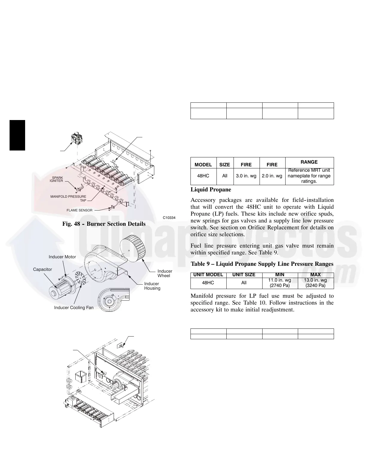
the tubes. See Fig. 48 and Fig. 50.
ROLLOUT
SWITCH
GAS
VALVE
SPARK
IGNITER
FLAME SENSOR
MANIFOLD PRESSURE
TAP
C10334
Fig. 48 -- Burner Section Details
Capacitor
Inducer
Housing
Inducer
Wheel
Inducer Cooling Fan
Inducer Motor
C10335
Fig. 49 -- Inducer Assembly
SIDE SHOT
LIMIT SWITCH
DOWN SHOT
LIMIT SWITCH
C10336
Fig. 50 -- Limit Switch Locations
Fuel Types and Pressures
Natural Gas
The 48HC unit is factory--equipped for use with Natural
Gas fuel at elevation under 2000 ft (610 m). See section
Orifice Replacement for information in modifying this
unit for installation at elevations above 2000 ft (610 m).
Gas line pressure entering the unit’s main gas valve must
be within specified ranges. See Table 7. Adjust unit gas
regulator valve as required or consult local gas utility.
Table 7 – Natural Gas Supply Line Pressure Ranges
UNIT MODEL UNIT SIZE MIN MAX
48HC All
4.0 in. wg
(996 Pa)
13.0 in. wg
(3240 Pa)
Manifold pressure is factory--adjusted for NG fuel use.
Adjust as required to obtain best flame characteristic. See
Table 8.
Table 8 – Natural Gas Manifold Pressure Ranges
UNIT
MODEL
UNIT
SIZE
HIGH
FIRE
LOW
FIRE
RANGE
48HC All 3.0 in. wg 2.0 in. wg
Reference MRT unit
nameplate for range
ratings.
Liquid Propane
Accessory packages are available for field--installation
that will convert the 48HC unit to operate with Liquid
Propane (LP) fuels. These kits include new orifice spuds,
new springs for gas valves and a supply line low pressure
switch. See section on Orifice Replacement for details on
orifice size selections.
Fuel line pressure entering unit gas valve must remain
within specified range. See Table 9.
Table 9 – Liquid Propane Supply Line Pressure Ranges
UNIT MODEL UNIT SIZE MIN MAX
48HC All
11.0 in. wg
(2740 Pa)
13.0 in. wg
(3240 Pa)
Manifold pressure for LP fuel use must be adjusted to
specified range. See Table 10. Follow instructions in the
accessory kit to make initial readjustment.
Table 10 – Liquid Propane Manifold Pressure Ranges
UNIT MODEL UNIT SIZE HIGH FIRE LOW FIRE
48HC All 11.0 in. wg 7.3 in. wg
Supply Pressure Switch
The LP conversion kit includes a supply low pressure
switch. The switch contacts (from terminal C to terminal
NO [Normally Open]) will open the gas valve power
whenever the supply line pressure drops below the
setpoint. See Fig. 51 and Fig. 52. The switch,
HK02LB008, opens contacts on pressure “fall” at
7.2”0.70” w.c. Contacts close on pressure rise above
10.2” w.c. If the low pressure remains open for 15 minutes
during a call for heat, the IGC circuit will initiate a
Ignition Fault (5 flashes) lockout. Reset of the low
pressure switch is automatic on rise in supply line
pressure. Reset of the IGC requires a recycle of unit
power after the low pressure switch has closed.
48HC

 Loading...


