46
IGC Board
IGC Board
C10337
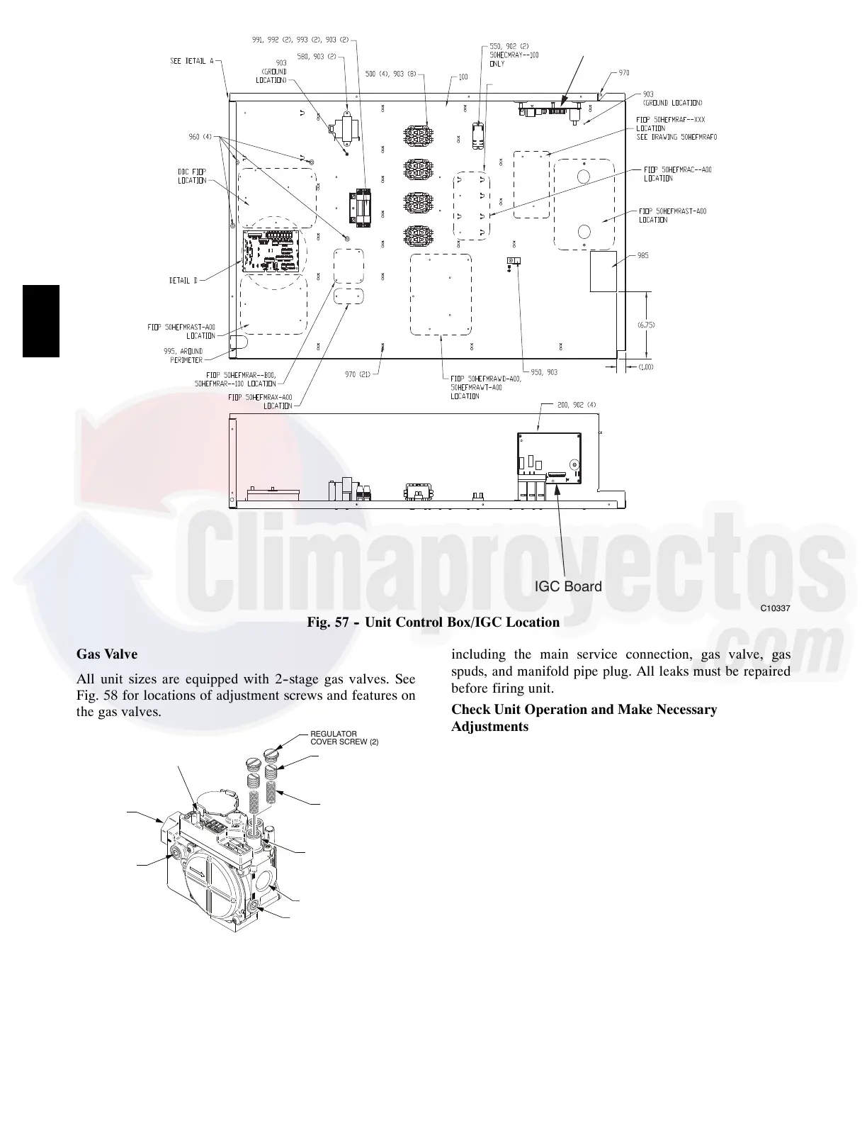
Fig. 57 -- Unit Control Box/IGC Location
Gas Valve
All unit sizes are equipped with 2--stage gas valves. See
Fig. 58 for locations of adjustment screws and features on
the gas valves.
PLASTIC ADJUST
SCREW (2)
REGULATOR SPRING (2)
(PROPANE - WHITE
NATURAL - SILVER)
LOW STAGE
GAS PRESSURE
REGULATOR
ADJUSTMENT
MANIFOLD
PRESSURE TAP
INLET
PRESSURE TAP
ON/OFF
SWITCH
REGULATOR
COVER SCREW (2)
NPT INLET
NPT OUTLET
C12066A
Fig. 58 -- Gas Valve
Adjusting Gas Valve Pressure Settings
IMPORTANT: Leak check (using a mixture of soapy
water or leak detection fluid) all gas connections
including the main service connection, gas valve, gas
spuds, and manifold pipe plug. All leaks must be repaired
before firing unit.
Check Unit Operation and Make Necessary
Adjustments
NOTE: Gas supply pressure at gas valve inlet must be
within specified ranges for fuel type and unit size. See
Tables 7, 8, 9, and 10.
1. Shut off electrical power supplies to unit and install
lockout tag.
2. Shut off manual gas shut off valve located on gas
supply line.
3. Remove manifold pressure tap plug from manifold
and connect pressure gauge or manometer. See Fig.
56.
4. Turn on electrical supply.
5. Open manual shut off valve, then turn on unit main
gas valve.
6. Set room thermostat to call for heat. Verify
high--stage heat operation before attempting to adjust
manifold pressure.
7. When main burners ignite, check all fittings,
manifold, and orifices for leaks.
48HC

 Loading...


