44
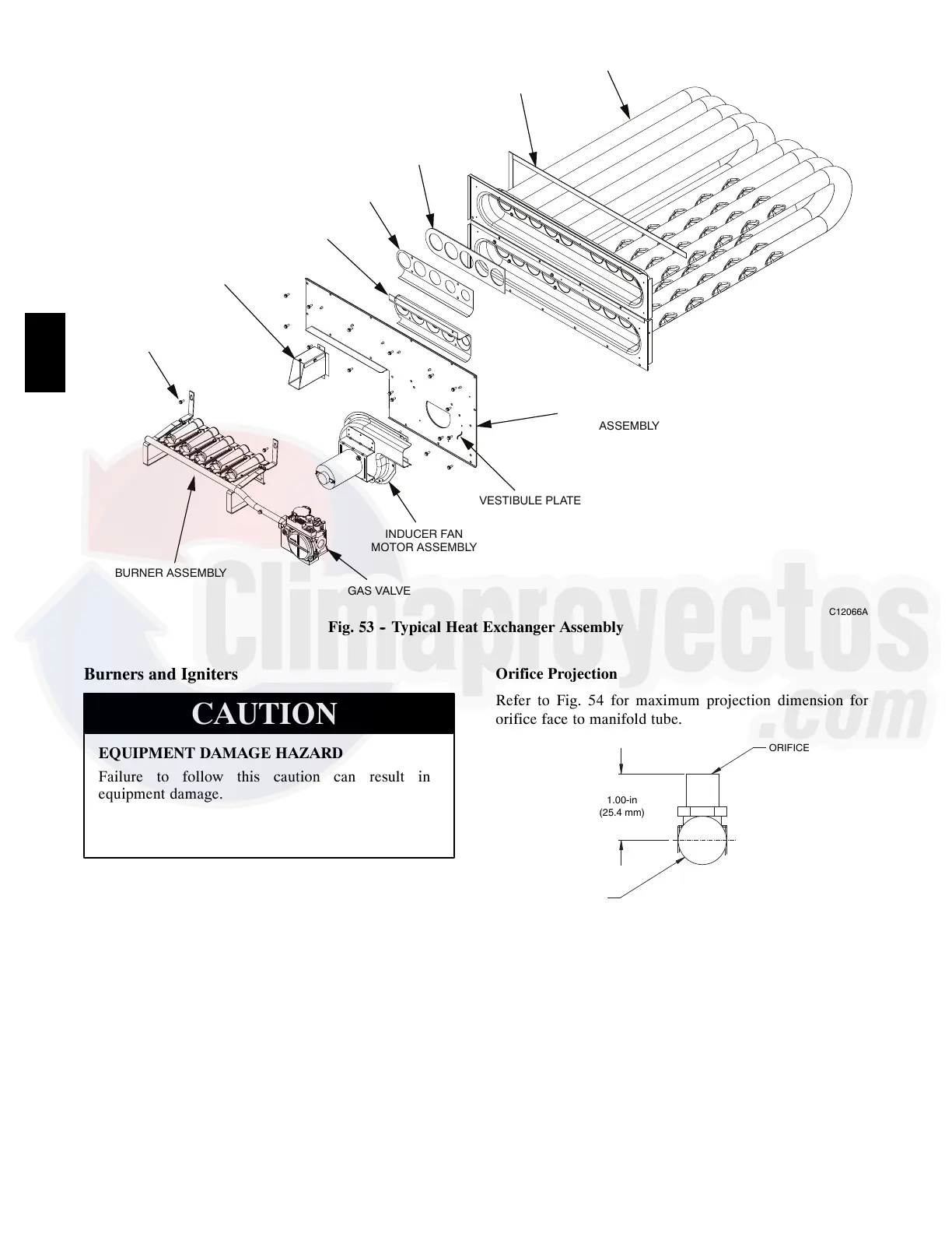
BURNER ASSEMBLY
GAS VALVE
INDUCER FAN
MOTOR ASSEMBLY
VESTIBULE PLATE
SUPPORT INSULATION
ASSEMBLY
HEATER TUBE
ASSEMBLY
SEAL STRIPS
(SPONGE RUBBER)
REGULATOR
GASKET
REGULATOR
RETAINER
WIND CAP ASSEMBLY
(SHOWN INVERTED
AS SHIPPED)
~
MOUNTING
SCREWS (2)
C12066A
Fig. 53 -- Typical Heat Exchanger Assembly
Burners and Igniters
EQUIPMENT DAMAGE HAZARD
Failure to follow this caution can result in
equipment damage.
When working on gas train, do not hit or plug
orifice spuds.
CAUTION
Main Burners
To access the burner section, open the heater access door
below the indoor fan panel. At the beginning of each
heating season, inspect for deterioration or blockage due
to corrosion or other causes. Observe the main burner
flames and adjust, if necessary. Flames should be conical
in shape and enter the heat exchanger tubes with minor
impingement on sheet metal flame components.
Orifice Projection
Refer to Fig. 54 for maximum projection dimension for
orifice face to manifold tube.
ORIFICE
1.00-in
(25.4 mm)
ANIFOLD
PIPE
C08211
Fig. 54 -- Orifice Projection
Removal and Replacement of Gas Train
See Figures 48, 53, and 55.
1. Shut off gas using the manual shutoff switch located
in the gas supply line.
2. Turn the gas valve ON/OFF knob to the OFF position.
3. Shut off power to unit and install lockout tag.
48HC

 Loading...


