31
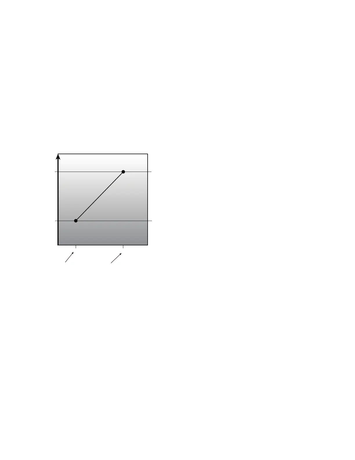
(HIGH AIR.Q DIFF), the control will modulate the damper
between the IAQ Minimum Position Curve and the Minimum
Position Curve in a linear manner as shown as the shaded area
in Fig. 19. Figure 21 shows the Min Position in Effect (EF-
FECTIVE MIN POS) relationship while the Commanded Fan
Speed (ECON CMD POSITION) is held at the maximum
speed.
ANALOG IAQ CTRL = 2 (Override IAQ)
Override IAQ is reserved for a future release.
ANALOG IAQ CTRL = 3 (Control Minimum Position)
An external 4 to 20 mA source is used to set the Min Position
in Effect (EFFECTIVE MIN POS). The 4mA signal corre-
sponds to 0% and the 20 mA signal corresponds to 100%. In
this mode, configuration such as Economizer minimum at
maximum fan speed (MIN POS @ MAX FAN), IAQ position
at maximum fan speed (IAQ POS @ MAX SPD) and the econ-
omizer minimum position and DCV minimum position curves
in Fig. 19 and Fig. 21 are not used. If the indoor fan is not oper-
ating, the economizer position will be zero. The actual damper
position may exceed the economizer Min Position in Effect
(EFFECTIVE MIN POS) to provide economizer cooling.
Fig. 21 — IAQ Minimum Position Curve
OUTDOOR AIR QUALITY (ANALOG INPUT)
The default for the Outdoor Air Quality (OAQ LEVEL) is
400 ppm CO
2
when the OAQ sensor is not assigned an input
channel. When OAQ Assigned channel (OAQ SENSOR
CHAN) is set for an analog input, that input channel will be
mapped to the Outdoor Air Quality (OAQ LEVEL). The out-
door air quality sensor provides a 4 to 20 mA signal corre-
sponding to 0 to 2000 ppm CO
2
. If a field supplied sensor has a
different range, the ppm display range must be reconfigured by
entering new values for the OAQ Sensor Value at 4mA (OAQ
PPM @ 4MA) and OAQ Sensor Value at 20mA (OAQ PPM @
20MA).
Pre-occupancy Purge
The control has the option for a pre-occupancy purge to refresh
the air in the space prior to occupancy. This feature is enabled
by setting PREOCC PURGE ENBL to Yes. This function is
also referred to as the IAQ purge function.
The IAQ Purge will operate under the following conditions:
• Purge is enabled
• the unit is in the unoccupied state
• Current Time is valid
• Next Occupied Time is valid
• time is one hour prior to next occupied period
• the OAT is greater than the lockout (PREOCC LOW LIMIT)
The IAQ Purge Position curve is created by applying the differ-
ence of the IAQ purge position at maximum fan speed
(PURGE POS @ MAX) and the Economizer minimum at max-
imum fan speed (MIN POS @ MAX FAN) in relationship to
the minimum position curve. The IAQ purge position at maxi-
mum fan speed (PURGE POS @ MAX) should be set to an
economizer position that brings in enough fresh air over an
hour period to remove contaminates and CO
2
during the unoc-
cupied period. When the preoccupancy purge function is active
(IN PREOCC PURGE?), the economizer Min Position in Ef-
fect (EFFECTIVE MIN POS) will follow the IAQ Purge Po-
sition curve.
Temperature Compensated Start
Space control set points are usually set to 2 different levels for
unoccupied period and occupied period. Unoccupied set points
saves energy, while occupied set points provide occupant com-
fort. The time period it takes for the RTU to bring the space
from its current condition in unoccupied mode to its occupied
set point is referred to as start bias time, or bias time. The algo-
rithm to calculate this bias time is called Temperature Compen-
sated Start. This is required for ASHRAE 90.1 compliance.
When temperature compensated start is running (TCS AC-
TIVE?) the control uses the occupied set points to control the
space.
When Temperature compensated start is enabled (ADAPTIVE
TCS?), no other configuration parameters are needed for this
algorithm, because the algorithm will automatically adjust the
Bias Time based on the data collected during the period of last
time optimal start. The inputs to the calculation algorithm in-
cludes space temperature, unoccupied set points, occupied set
points, outdoor air temperature, and supply air temperature.
Bias time is changed dynamically per RTU operation.
When Temperature compensated start is disabled (ADAPTIVE
TCS?), the control will use the User Temperature compensated
Start bias time (USER TCS BIASTIME) in determining when
to start controlling to the occupied set points. If the User Tem-
perature compensated Start bias time (USER TCS BIAS-
TIME) is set to zero, the control will switch to the occupied
setpoints at the time of occupancy.
Linkage
The SystemVu™ controller will support 3V™, VAV and
VVT
®
zoning system on a CCN system or Open VVT and
VAV systems on a BACnet MS/TP System. All that is required
is to configure the Open or 3V Master zone to use the System-
Vu rooftop unit as its airsource. The SystemVu control will
need to be configured for the proper network protocol (BAS
PROTOCOL) and set for Space Sensor Control (UNIT CTRL
TYPE). The SystemVu controller will reply to the zoning sys-
tem and change its operating parameters to meet the demand of
the zoning system. Status of this process can be viewed in the
airside linkage tab of the property pages in the i-Vu
®
applica-
tion or by viewing the linkage maintenance table with a CCN
tool.
Carrier Comfort Network
®
(CCN) Operation
The SystemVu controller can be configured to connect to a
CCN system. The SystemVu controller has one RS-485 BMS
port that can be configured from the local display for BACnet
or CCN. The BMS configuration parameters can be found in
the SETTINGS NETWORK SETTINGS submenu. The
first configuration is the BMS system for CCN systems change
this configuration from BACnet to CCN then set the CCN
BAUD rate, the bus and element number and you will be able
to find the controller with any CCN tool then upload the CCN
tables in the controller for use by the tool.
VENTILATION FOR PEOPLE
VENTILATION FOR SOURCES
INCREASING VENTILATION
MIN POS @
MAX FAN
IAQ POS @
MAX FAN
100 700 INSIDE/OUTSIDE CO
2
DIFFERENTIAL
LOW AIR.Q DIFF HIGH AIR.Q FIFF

 Loading...


