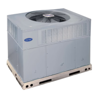
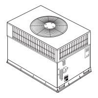
13
NOTE: Install a filter drier whenever the system has been opened
for repair.
3. Add a small charge of R --22 refrigerant vapor to system and
leak--test unit.
4. Recover refrigerant from refrigerant system and evacuate to
500 microns if no additional leaks are found.
5. Charge unit with R--22 refrigerant, using a volumetric
charging cylinder or accurate scale. Refer to unit rating plate
for required char ge. Be sure to add extra refrigerant to
compensate for internal volume of filter drier.
STEP 2—START--UP HEATING AND MAKE ADJ UST-
MENTS
Complete the required procedures given in the Pre--Start--Up
section before starting the unit. Do not jumper any safety devices
when operating the unit. Make sure that burnerorifices are properly
aligned. Unstable operation my occur when the burner orifices in
the manifold are misaligned.
Follow the lighting instructions on the heating section operation
label (located inside the burner or blower access door) to start the
heating section.
NOTE: Make sure that gas supply has been purged, and that all gas
piping has been checked for leaks.
MANIFOLD PIPE PLUG
LOW-VOLTAGE
SPLICE BOX
A07568
Fig. 13 -- Burner Assembly
MANIFOLD
BURNER
BURNER FLAME
C99021
Fig. 14 -- Monopoly Burner
CHECK HEATING CONTROL
Start and check the unit for proper heating control operation as
follows (see furnace lighting instructions located inside burner or
blower access panel):
1. Place room thermostat SYSTEM switch in the HEAT
position and the fan switch is placed in AUTO position.
2. Set the heating temperature control of the thermostat above
room temperature.
3. The induced-- draft motor will start.
4. After a call for heating, the main burner should light within
5 sec. If the burners do not light, there is a 22 --sec. delay
before another 5--sec. try. If the burners still do not light, this
sequence is repeated. If the burners do not light within 15
minutes from the initial call for heat, there is a lockout. To
reset the control, break the 24--v power to W.
5. The evaporator fan will turn on 45 sec. after the flame has
been established. The evaporator fan will turn off 45 sec.
after the thermostat has been satisfied.
CHECK GAS
INPUT
Check gasinput and manifold pressureafter unitstart--up (SeeTable
3). If adjustment is required proceed as follows:
S The rated gas inputs shown in Table 3 are for altitudes
from sea level to 2000 ft above sea level. These inputs are
based on natural gas with a heating value of 1050 Btu/ft
3
at 0.65 specific gravity, or propane gas with a heating
value o f 2500 Btu/ft
3
at 1.5 specific gravity .
S For elevations above 2000 ft (610 m), reduce input 4%
for each 1000 ft (305 m) above sea level. For example at
2001 ft (610 m) a 12% total derate is required.
S When the gas supply being used has a different heating
value or specific gravity, refer to nationaland local codes,
or contact your distributor to determine the required
orifice size.
UNIT DAMAGE HAZARD
Failure to follow this caution may result in reduced unit and/or
component life.
Do No t redrill an orifice. Improper drilling (burrs,
out-- of--round holes, etc.) can cause excessive burner noise
and misdirection of burner flame. If orifice hole appears
damaged or it is suspected to have been redrilled, check orifice
hole with a numbered drill bit of correct size.
!
CAUTION
ADJUST GAS INPUT
The gas input to the unit is determined by measuring the gas flow
at the meter or by measuring the manifold pressure. Measuring the
gas flow at the meter is recommended for natural gas units. The
manifold pressure must be measured to determine the input of
propane gas units.
Measure Gas Flow (Natural Gas
Units)
Minor adjustment to the gas flow can be made by changing the
manifold pressure. The manifold pressure must be maintained
between 3.4 and 3.6 in. wc.
If larger adjustments are required, change main burner orifices
following the recommendations of national and local codes.
NOTE: All other appliances that use the same meter must be turned
off when gas flow is measured at the meter.
Proceed as follows:
1. Turn off gas supply to unit.
48SD

 Loading...