14
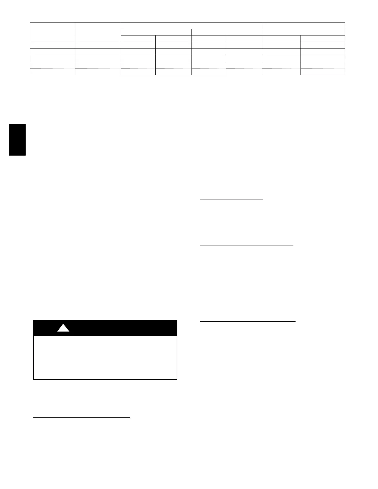
Table 3—Heating Inputs
HEATING INPUT
(BTUH)
GAS SUPPLY PRESSURE (IN. WC)
Natural{ Propane*{
.
Min Max Min Max Natural{ Propane*†
40,000 2 4.0 13.0 4.0 13.0 3.5 3.5
60,000 2 4.0 13.0 4.0 13.0 3.5 3.5
90,000 3 4.0 13.0 4.0 13.0 3.5 3.4
115,000 3 4.0 13.0 4.0 13.0 3.5 3.7
130,000 3 4.0 13.0 4.0 13.0 3.5 3.5
*When a unit is converted to propane, different size orifices must be used. See separate, natural--to--propane conversion kit instructions.
{Based on altitudes from sea level to 2000 ft above sea level. For altitudes above 2000 ft, reduce input rating 4 percent for each additional 100 0 ft above sea level. In Canada,
from 2000 ft above sea level to 4500 ft above sea level, derate the unit 10 percent.
2. Remove pipe plug on manifold (See Fig. 13) and connect
manometer. Turn on gas supply to unit.
3. Record numberof secondsforgas metertest dialto makeone
revolution.
4. Divide number of seconds in Step 3 into 3600 (number of
seconds in one hr).
5. Multiply result of Step 4 by the number of cubic feet (cu ft)
shown for one revolution of test dial to obtain cubic feet (cu
ft) of gas flow per hour.
6. Multiply result of Step 5 by Btu heating value of gas to
obtaintotalmeasured input in Btuh. Comparethisvaluewith
heating input shown in Table 3 (Consult the local gas
supplier if the heating value of gas is not known).
EXAMPLE: Assume that the size of test dial is 1 cu ft, one
revolution takes 32 sec, and the heating value of the gas is 1050
Btu/ft
3
. Proceed as follows:
1. 32 sec. to complete one revolution.
2. 3600 ÷ 32 = 112.5.
3. 112.5x1=112.5ft3ofgasflow/hr.
4. 112.5 x 1050 = 118,125 Btuh input.
If the desired gas input is 115,000 Btuh, only a minor change in the
manifold pressure is required.
Observe manifold pressure and proceed as follows to adjust gas
input:
1. Removecover screw overregulatoradjustmentscrew on gas
valve.
2. Turn regulator adjustment screw clockwise to increase gas
input, or turn regulator adjustment screw counterclockwise
to decrease input. Manifold pressure must be between 3.4
and 3.6 in. wc.
FIRE AND UNIT DAMAGE HAZARD
Failure to follow this warning could result in personal injury
or death and/or property damage.
Unsafe operation of the unit may result if manifold pressure is
outside this range.
!
WARNING
3. Replace cover screw cap on gas valve.
4. Turn off gas supply to unit. Remove manometer from
pressure tap and replace pipe plug on gas valve. Turn on gas
to unit and check for leaks.
Measure Manifold Pressure (Propane
Units)
The main burner orifices on a propane gas unit are sized for the unit
rated input when the manifold pressure reading matches the level
specified in Table 3.
Proceed as follows to adjust gas input on a propane gas unit:
1. Turn off gas to unit.
2. Removepipeplug on manifold andconnect manometer(See
Fig. 13).
3. Turn on gas to unit.
4. Remove cover screw over regulator adjustmentscrew on gas
valve.
5. Adjust regulator adjustment screw to the correct manifold
pressure, as specified in Table 3. Turn adjusting screw
clockwise to increase manifold pressure, or turn adjusting
screw counterclockwise to decrease manifold pressure.
6. Replace cover screw.
7. Turn off gas to unit. Remove manometer from pressure tap.
Replace pipe plug on gas valve, then turn on gas to unit.
Check for leaks.
CHECK BURNER
FLAME
With burner access panel removed, observe the unit heating
operation. Watch the burner flames to see if they are light blue and
soft in appearance, and that the flames are approximately the same
for each burner. Propane will have blue flame (See Fig. 14). Refer
to the Maintenance section for information on burner removal.
AIRFLOW AND TEMPERATURE
RISE
The heating section for each size unit is designed and approved for
heating operation within the temperature--rise range stamped on the
unit rating plate.
Table 8 shows the approved temperature rise range for each heating
input, and the air delivery cfm at various temperature rises. The
heating operation airflow must produce a temperature rise that falls
within the approved range.
Refer to Indoor Airflow and Airflow Adjustments section to adjust
heating airflow when required.
HEATING SEQUENCE OF OPERA
TION
(See Fig. 15--17 and unit wiring label.)
On a call for heating, terminal W of the thermostat is energized,
starting theinduced-- draft motor. When thehall-- effectsensoron the
induced--draft motor senses that it has reached the required speed,
the burner sequence begins. This function is performed by the
integrated gas control (IGC). The indoor (evaporator)-- fan motor is
energized 45 sec after flame is established. When the thermostat is
satisfied and W is de--energized, the burners stop firing and the
indoor (evaporator) fan motor shuts off after a 45--sec time-- off
delay.
Please note that the ignition control board (IGC) has the capability
to automatically reduce theindoor fan motor onand off delays in the
event of high duct static and/or partially--clogged filter. An
adjustment of fan delays by the ignition control board is indicated
by a flash code “1” on the LED on the IGC.
An LED (light--emitting diode) indicator is provided on the control
board to monitor operation. The control board is located by
removing the burner access panel. During normal operation, the
LED is continuously on (See Table 4 for status codes).
48SD
48SD

 Loading...