EasyManua.ls Logo

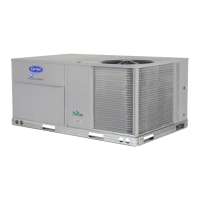
Carrier 48TC*D User Manual

Carrier 48TC*D
98 pages
To Next Page IconTo Next Page
Page #1 background imageLoading...
Page #1 background image
48TC*D08---D14
Nominal 7.5 to 12.5 Tons
Wi t h Pu ro n (R---410A) Refrigerant
Service and Maintenance Instructions
TABLE OF CONTENTS
SAFETY CONSIDERATIONS 1....................
UNIT ARRANGEMENT AND ACCESS 2...........
SUPPLY FAN (BLOWER) SECTION 4..............
COOLING 6....................................
PURONR (R--410A) REFRIGERANT 8..............
COOLING CHARGING CHARTS 10................
CONVENIENCE OUTLETS 16....................
SMOKE DETECTORS 17.........................
PROTECTIVE DEVICES 24.......................
GAS HEATING SYSTEM 25......................
CONDENSER COIL SERVICE 35..................
PREMIERLINKt CONTROL 36...................
RTU--MP CONTROL SYSTEM 44..................
ECONOMI$ER SYSTEMS 57......................
WIRING DIAGRAMS 66.........................
PRE--START--UP 69..............................
START--UP, GENERAL 69........................
START--UP, PREMIERLINK CONTROL 71..........
START--UP, RTU--MP CONTROL 71................
OPERATING SEQUENCES 75.....................
FASTENER TORQUE VALUES 85.................
APPENDIX I. MODEL NUMBER SIGNIFICANCE 87.
APPENDIX II. PHYSICAL DATA 88................
APPENDIX III. FAN PERFORMANCE 90...........
APPENDIX IV. WIRING DIAGRAM LIST 96........
APPENDIX V. MOTORMASTER SENSOR
LOCATIONS 97.................................
UNIT ST ART-UP CHECKLIST 98..................
SAFETY CONSIDERATIONS
Installation and servici ng of air-conditioning equipment
can be hazardous due to system pressure and electrical
compone nts. Only trained and qualifi ed service personnel
should install, repair, or service air-conditioning
equipment. Untrained personnel can perform the basic
maintenance functions of replacing filters. Trained service
personnel should perform all other operati ons.
When working on air-conditioning equipment, observe
precautions in the literature, tags and labels attached to
the unit, and other safety precautions that may apply.
Follow all safety codes. Wear safety glasse s and work
gloves. Use quenching cloth for unbrazing operations.
Have fire extinguishers avail able for all brazing
operations.
Follow all safety codes. Wear safety glasse s and work
gloves. Use quenching cloth for brazi ng operat ions. Have
fire extinguisher available. Read these instructions
thoroughly and follow all warnings or cautions attache d to
the unit. Consult local building codes and National
Electrical Code (NEC) for special requirements.
Recognize safety information. This is the safety--alert
symbol
. When you see this symbol on the unit and in
instructions or manuals, be alert to the potential for
personal injury.
Understand the signal words DANGER, WARNING, and
CAUTION. These words are used with the safety-- alert
symbol. DANGER identifies the most serious hazards
which will result in severe personal i njury or death.
WARNING signifies a hazard which could result in
personal injury or de ath. CAUTION is used to identify
unsafe practices which may result in minor personal
injury or product and property da mage. NOTE is used to
highlight suggestions which will result in enhanced
installation, reliability, or operation.
Question and Answer IconNeed help?

Do you have a question about the Carrier 48TC*D and is the answer not in the manual?

Carrier 48TC*D Specifications

General IconGeneral
Model Number48TC*D
RefrigerantR-410A
TypeAir Conditioner
Voltage208/230V or 460V
Sound LevelVaries by model, typically 70-80 dBA
Dimensions (L x W x H)Varies by model
WeightVaries by model

Summary

SAFETY CONSIDERATIONS

UNIT ARRANGEMENT AND ACCESS

Routine Maintenance

Quarterly Inspection

Key tasks for quarterly checks and initial setup.

Seasonal Maintenance

Tasks to be performed at the beginning of each season.

Air Filters and Screens

Return Air Filters

Instructions for accessing and replacing disposable fiberglass return air filters.

SUPPLY FAN (BLOWER) SECTION

Supply Fan (Belt-Drive)

Description of the belt-drive system for the supply fan.

Belt

Guidance on checking belt condition and tension quarterly.

COOLING

Condenser Coil

Description of the NOVATION Heat Exchanger Technology condenser coil.

Evaporator Coil

Description of the traditional round-tube, plate-fin evaporator coil.

Coil Maintenance and Cleaning Recommendation

General recommendations for coil maintenance and cleaning.

PURON® (R-410A) REFRIGERANT

Refrigerant Charge

How to determine and adjust the refrigerant charge amount.

Low-Charge Cooling

Using cooling charging charts to adjust refrigerant for superheat.

COOLING CHARGING CHARTS

Table 1 - Cooling Service Analysis

Compressors

Compressor Rotation

How to determine and correct compressor rotation direction.

Condenser-Fan Adjustment

Condenser-Fan Adjustment (D08-D12 size)

Steps for adjusting the condenser fan height for D08-D12 models.

Condenser-Fan Adjustment (D14 size)

Steps for adjusting the condenser fan height for D14 models.

Troubleshooting Cooling System

SMOKE DETECTORS

System

Overview of the smoke detector system components and function.

Controller

Description of the smoke detector controller and its LEDs.

Sensor

Description of the smoke detector sensor and its components.

Smoke Detector Locations

Details on the location and installation of smoke detector sensors.

FIOP Smoke Detector Wiring and Response

Sensor and Controller Tests

Sensor Alarm Test

Procedure to test the sensor's ability to signal an alarm state.

Controller Alarm Test

Procedure to test the controller's ability to initiate an alarm state.

Troubleshooting

Controller's Trouble LED is On

Steps to diagnose when the controller's Trouble LED is on.

Controller's Trouble LED is Flashing

Steps to diagnose when the controller's Trouble LED is flashing.

Controller's Power LED is Off

Steps to diagnose when the controller's Power LED is off.

PROTECTIVE DEVICES

Compressor Protection

Overview of compressor protection mechanisms.

High Pressure Switch

Details on the high pressure switch operation and settings.

Low Pressure Switch

Details on the low pressure switch operation and settings.

GAS HEATING SYSTEM

General

General description of the gas heat exchanger system.

Fuel Types and Pressures

Information on natural gas and propane fuel types and pressures.

Burners and Igniters

Main Burners

Inspection of main burners for deterioration or blockage.

Removal and Replacement of Gas Train

Cleaning and Adjustment

Procedures for cleaning and adjusting burners.

Burner Ignition

Orifice Replacement

Minimum Heating Entering Air Temperature

Troubleshooting Heating System

Burners Will Not Ignite.

Common causes and remedies for burner ignition failure.

Inadequate Heating.

Causes and remedies for inadequate heating performance.

Burners Will Not Turn Off.

Causes and remedies for burners not shutting off.

CONDENSER COIL SERVICE

Repairing NOVATION Condenser Tube Leaks

Information on repairing leaks in NOVATION condenser coil tubes.

Replacing NOVATION Condenser Coil

Procedure for replacing the NOVATION condenser coil.

PREMIERLINK™ CONTROL

EconoMi$er IV Control Modes

Overview of EconoMi$er IV control modes.

Outdoor Dry Bulb Changeover

How outdoor dry bulb temperature controls the economizer.

Space Sensors

Outdoor Air Temperature (OAT) Sensor

Information about the OAT sensor and its characteristics.

Indoor Air Quality (CO2 sensor)

Wiring the Indoor Air Quality Sensor

Steps for wiring the indoor air quality sensor.

Economizer controls

Outdoor Air Enthalpy Control (PNO HH57AC077)

Using outdoor air enthalpy control with EconoMi$er2.

Differential Enthalpy Control

Using differential enthalpy control for economizer operation.

Return Air Enthalpy Sensor

Mounting and wiring the return air enthalpy sensor.

Outdoor Air Quality Sensor (PNO 33ZCSENCO2 plus weatherproof enclosure)

Wiring the Outdoor Air CO2 Sensor

Steps for wiring the outdoor air CO2 sensor.

RTU-MP CONTROL SYSTEM

PremierLink Filter Switch Connection

How to connect the PremierLink filter switch input.

Fan Status

Configuration for the supply fan status input.

Remote Occupied Switch

Connecting the PremierLink remote occupied switch.

CCN Communication Bus

General

Explanation of communication protocols used by control devices.

RTU-MP CONTROL SYSTEM

RTU-MP Controller Inputs and Outputs

Space Temperature Sensor

Information about the RTU-MP space temperature sensor.

Supply Air Temperature (SAT) Sensor

Description of the SAT sensor used with RTU-MP.

Outdoor Air Temperature (OAT) Sensor

Description of the OAT sensor used with RTU-MP.

Economizer controls

Connect T-59

Instructions for connecting the T-59 space sensor.

Communication Wiring - Protocols

General

Explanation of communication protocols used by control devices.

Local Access

BACview Handheld

Description of the BACview handheld interface.

Virtual BACview

Description of the Virtual BACview software.

RTU-MP Troubleshooting

Communication LEDs

Explanation of communication LED indicators.

Alarms

Safety Chain Alarm

Explanation of the Safety Chain Alarm.

Fire Shutdown Alarm

Explanation of the Fire Shutdown Alarm.

Space Temp Sensor Failure

Explanation of the Space Temp Sensor Failure alarm.

SAT Sensor Alarm

Explanation of the SAT Sensor Alarm.

Third Party Networking

Troubleshooting third-party communication and networking.

ECONOMISER SYSTEMS

Economizer Controls

How economizer dampers are used for cooling and IAQ.

EconoMi$er IV Standard Sensors

Outdoor Air Temperature (OAT) Sensor

Information about the OAT sensor and its temperature range.

EconoMi$er IV Control Modes

Outdoor Dry Bulb Changeover

How outdoor dry bulb temperature controls the economizer.

Differential Dry Bulb Control

Outdoor Enthalpy Changeover

Indoor Air Quality (IAQ) Sensor Input

Demand Control Ventilation (DCV)

CO2 Sensor Configuration

EconoMi$er IV Preparation

Differential Enthalpy

Testing procedure for differential enthalpy control.

Single Enthalpy

Testing procedure for single enthalpy control.

DCV (Demand Controlled Ventilation) and Power Exhaust

Testing DCV and Power Exhaust functions.

WIRING DIAGRAMS

PRE-START-UP

Perform initial start-up:

General steps for preparing the unit for initial start-up.

START-UP, GENERAL

Unit Preparation

Ensure unit is installed per instructions and codes.

Gas Piping

Check gas piping for leaks before start-up.

Cooling

Heating

START-UP, PREMIERLINK™ CONTROLS

Perform System Check-Out

Performing system check-out before operation.

Initial Operation and Test

Procedures for initial unit operation and testing.

START-UP, RTU-MP CONTROL

Field Service Test

Using the Field Service Test function for proper start-up.

Configuration

Unit

Configuration submenus related to the unit.

Cooling

Configuration settings related to cooling operation.

Number of Compressor Stages

Setting the number of mechanical cooling stages.

Cooling/Econ SAT Low Setpt

Heating

Heating SAT High Setpt

Setting the maximum supply air temperature for heating.

Heating Lockout Temp

Defining the maximum outdoor air temperature for heating.

Inputs

Input 3

Configuration options for Input 3.

Input 5

Configuration options for Input 5.

Input 8

Configuration options for Input 8.

Input 9

Configuration options for Input 9.

Space Sensor Type

Selecting the type of space sensor installed.

Economizer

Economizer Minimum Position

Setting the minimum economizer damper position.

Economizer High OAT Lockout

Setting the high outdoor air temperature lockout for economizer.

Power Exhaust Setpt

Setting the power exhaust fan activation point.

IAQ

Indoor Air Quality control parameters.

Heating With EconoMi$er IV

Demand Controlled Ventilation

Supplemental Controls

Compressor Lockout Relay (CLO)

Description and function of the Compressor Lockout Relay.

Phase Monitor Relay (PMR)

Function of the Phase Monitor Relay for power protection.

PremierLink™ Control

THERMOSTAT MODE

Configuring PremierLink for Thermostat Mode operation.

Indoor Fan

Conditions for indoor fan operation with PremierLink.

Cooling

How PremierLink controls cooling operation.

Heating

Indoor Air Quality

CCN SENSOR MODE

RTU-MP Sequence of Operation

Scheduling

How scheduling is used to start heating or cooling.

Always Occupied (Default Occupancy)

Setting the unit to run continuously.

Local Schedule

Operating according to a configured local schedule.

Holiday Schedule

BACnet Schedule

Indoor Fan

Cooling

Economizer

Heating

Indoor Air Quality

FASTENER TORQUE VALUES

APPENDIX I. MODEL NUMBER SIGNIFICANCE

APPENDIX II. PHYSICAL DATA

APPENDIX III. FAN PERFORMANCE

ELECTRICAL INFORMATION

MCA/MOCP DETERMINATION

APPENDIX IV. WIRING DIAGRAM LIST

APPENDIX V. MOTORMASTER SENSOR LOCATIONS

UNIT START-UP CHECKLIST

II. PRE-START-UP

Checklist items to verify before unit start-up.

III. START-UP

Sections for recording electrical, temperature, and pressure data.
Related product manuals