8
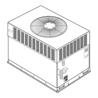
Table 1—Physical Data Con’t -- Unit 48XT--A
UNIT SIZE A48090 A481 15 A48130 A60090 A60115 A60130
NOMINAL COOLING CAPACITY (ton) 4 4 4 5 5 5
NOMINAL HEATING CAPACITY (Btu) 90,000 115,000 130,000 90,000 115,000 130,000
SHIPPING WEIGHT (lb)
(kg)
575
261
575
261
575
261
618
280
618
280
618
280
COMPRESSORS
Quantity
Two--Stage Scroll
1
REFRIGERANT: PURON (R--410A)
Quantity (lb)
(kg)
15.5
7.0
15.5
7.0
15.5
7.0
16.0
7.3
16.0
7.3
16.0
7.3
EXPANSION DEVICE--HEATING AccuRater
Orifice OD (in.) -- Left 0.038 0.038 0.038 0.046 0.046 0.046
Orifice OD (in.) -- Right 0.046 0.046 0.046 0.046 0.046 0.046
EXPANSION DEVICE--COOLING TXV
Size 4Ton 4Ton 4Ton 5Ton 5Ton 5Ton
OUTDOOR FAN
Nominal Cfm
Diameter (in.)
(mm)
Motor Hp (Rpm)
3300
22
559
1/4 (1 100)
3300
22
559
1/4 (1 100)
3300
22
559
1/4 (1 100)
3300
22
559
1/3 (1 110)
3300
22
559
1/3 (1 110)
3300
22
559
1/3 (1 110)
OUTDOOR COIL
Rows...Fins/in.
Face Area (sq ft)
2...21
19.4
2...21
19.4
2...21
19.4
2...21
23.3
2...21
23.3
2...21
23.3
INDOOR COIL
Rows...Fins/in.
Face Area (sq ft)
3...17
5.7
3...17
5.7
3...17
5.7
4...17
5.7
4...17
5.7
4...17
5.7
INDOOR FAN
Nominal Airflow (Cfm)
Comfort Variable based on Comfort Roll back (see User Interface instructions for more information).
Efficiency 1400 1400 1400 1750 1750 1750
Max 1600 1600 1600 2000 2000 2000
Fu rnace (gas ht.) airflow--- Low Stage 815 1215 1255 845 1215 1255
Furnace (gas ht.) airflow ---High Stage 1385 1885 1875 1300 1910 1920
Size in.
(mm)
11x10
279x254
11x10
279x254
11x10
279x254
11x10
279x254
11x10
279x254
11x10
279x254
Motor HP (RPM) 3/4 3/4 3/4 1 1 1
FURNACE SECTION*
Burner Orifice No. (Qty...Drill Size)
Natural Gas
3...38 3...33 3...31 3...38 3...33 3...31
HIGH --PRESSURE SWITCH (psig)
Cut--out
Reset (Auto)
670 ± 10
470
± 25
HIGH --PRESSURE SWITCH 2 (psig)
(Compressor Sol en oid)
Cut--out
Reset (Auto)
565 ± 15
455 ± 15
LOSS--OF--CHARGE /
LOW--PRESSURE SWITCH
(Liquid Line) (psig)
Cut--out
Reset (auto)
23 ± 5
55
± 5
RETURN--AIR FIL TERS Throwaway (in.)†
(mm)
24x36x1
610x914x25
*Based on altitude of 0 to 2000 ft ( 0 ---610 m).
{Recommended filter sizes for field---installed air filter grilles mounted on the wall or ceiling of the conditioned structure. Required filter sizes shown are based on
the larger of the ARI (Air Conditioning and Refrigeration Institute) rated cooling airflow or the heating airflow velocity of 300 ft/minute for throwaway type or 450
ft/minute for high ---capacity type. Air filter pressure drop for non ---standard filters must not exceed 0.08 in. wc.
Select and Install Ductwork
The design and installation of the duct system must be in
accordance with the standards of the NFPA for installation of
non--residence type air conditioning and ventilating systems,
NFPA 90A or residence type, NFPA 90B and/or local codes and
ordinances.
Select and size ductwork, supply--air registers, and return air grilles
according to ASHRAE (American Society of Heating,
Refrigeration, and Air Conditioning Engineers) recommendations.
The unit has duct flanges on the supply-- and return--air openings
on the side of the unit.
When designing and installing ductwork, consider the following:
1. All units should have field--supplied filters or accessory
filter rack installed in the return--air side of the unit.
Recommended sizes for filters are shown in Table 1.
2. Avoid abrupt duct size increases and reductions. Abrupt
change in duct size adversely affects air performance.
48XT-- A
 Loading...