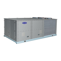
This document provides installation, start-up, and service instructions for Carrier Single-Package Cooling Units, specifically models 50CD/CH008.
Function Description:
The Carrier Single-Package Cooling Units are designed for air conditioning applications. They are self-contained units that combine the compressor, condenser, and evaporator in a single package. The 50CD/CH008 models can be equipped with an optional outdoor air damper or an economizer to mix outdoor air with return air, enhancing ventilation and energy efficiency. These units are suitable for both roof-mount and slab-mount installations, offering flexibility in placement. The system includes a belt-drive evaporator fan for high static applications, a condenser fan, and a compressor for refrigerant circulation. Safety features include high-pressure and low-pressure switches, and a Cycle-LOC™ protection device to shut down the unit on safety trips.
Important Technical Specifications:
- Unit Size: 50CD/CH008
- Operating Weight:
- Unit: 730 lb
- With Economizer: 790 lb
- Roof Curb (14 in.): 120 lb
- Compressor:
- Type: 1-BRE2 Copeland
- Oil: 124 oz
- Refrigerant: R-22 (Capillary Control), Charge: 105 lb
- Condenser Coil: Copper Tubes, Aluminum Fins, 2 Rows, 13.9 Fins/in., 15.6 sq ft Total Face Area
- Condenser Air Fan:
- Nominal Cfm: 4100
- Diameter: 1-22 in.
- Motor Hp: 1/2 Hp (1075 Rpm)
- Evaporator Coil: Copper Tubes, Aluminum Fins, 3 Rows, 13.9 Fins/in., 8.2 sq ft Total Face Area
- Evaporator Air Fan:
- Quantity/Size: 1-12 x 9 in.
- Nominal Cfm: 3000
- Minimum and Maximum Cfm: 2250-3650 (Standard Motor), 2250-3750 (Optional Motor)
- Rpm Range: 652-924
- Maximum Allowable Rpm: 924
- Motor Pulley Pitch Diameter: 2.4-3.4 in.
- Fan Pulley Pitch Diameter: 12.7 in.
- Belt No./Type: 1-A51
- Speed Change per Full Turn of Moveable Pulley Flange: 54 Rpm
- Moveable Pulley Maximum Full Turns from Closed Position: 5
- Factory Setting - Full Turns Open: 3
- Factory Speed Setting: 760 Rpm
- Motor Hp (Service Factor): 1 Hp (1.4) Standard, 1.5 Hp (1.3) Optional
- High-Pressure Switch: Cutout: 426 ± 7 psig, Reset: 320 ± 20 psig
- Low-Pressure Switch (Liquid Line): Cutout: 27 ± 4 psig, Reset: 67 ± 7 psig
- Outdoor Air Inlet Screens (Economizer): 2-19 x 31 x 1/2 in. (None on 50CH008)
- Return Air Filters: Disposable, 2-16 x 20 x 1 in. or 2-20 x 20 x 1 in. (None on 50CH008)
- Electrical Data:
- Nominal V-PH-HZ: 208/230-3-60, 460-3-60
- Voltage Range: 187-254V (208/230V), 414-508V (460V)
- Compressor RLA: 32.5A (208/230V), 15.2A (460V)
- Compressor LRA: 183A (208/230V), 91.1A (460V)
- Outdoor Fan Motor (OFM) FLA: 2.9A (208/230V), 1.5A (460V)
- Indoor Fan Motor (IFM) FLA: 8.0A (208/230V), 2.9A (460V)
- Electric Heaters (Kw/FLA): Various options from 9.3 Kw (20-23 FLA) to 29.6 Kw (35.7 FLA)
- Minimum Circuit Amps (Min Ckt) and Maximum Overcurrent Protection (MOCP) are provided for various configurations.
- Voltage Unbalance: Operating voltage to compressor must be balanced within 2% (voltage) and 10% (current).
Usage Features:
- Installation: Units can be roof-mounted (50CD008) or slab-mounted (50CH008). Roof curbs are assembled and installed separately, with critical gasketing for water integrity. Slab mounts require a level concrete slab, 8 inches thick with 4 inches above grade, and a gravel apron for airflow and drainage.
- Positioning: Units should be positioned to prevent snowdrifts from blocking coils and outdoor air intake, with adequate clearance for airflow, safety, and service access. Avoid indoor locations or areas near exhaust vents.
- Ductwork: Field-fabricated ductwork must be secured to the roof curb or unit flanges and insulated/weatherproofed. Cabinet return air static should not exceed 0.35 in. with economizer or 0.40 in. without.
- Optional Manual Outdoor Air Damper (50CD008): Shipped broken down, it can be assembled and adjusted to control the percentage of outdoor air intake.
- Condensate Drain: A preformed drain hose is supplied and must be routed through the evaporator basepan and unit base rail, with a trap at least 4 inches deep and protected against freeze-up.
- Field Power Supply: Units are factory wired for nameplate voltage. Transformers may need reconnection for 208-volt installations. All wiring must comply with National Electrical Code and local requirements.
- Field Control Wiring: Requires a Carrier-approved accessory thermostat assembly, located on a solid wall to sense average temperature. Thermostat wires (18-gage for 0-50 ft, 16-gage for 50-75 ft) are routed through a corner post raceway to the 24-v barrier in the control box. Heat anticipator settings are provided.
- Return Air Filters (50CD008): Correct filters must be installed in filter tracks, and the unit should not be operated without them.
- Outdoor Air Inlet Screens (50CD008): Must be in place before operating the unit.
- Economizer Section (50CD008): Optional economizer is shipped broken down and assembled on-site. It modulates outdoor air intake based on ambient temperature and building ventilation needs. It includes an economizer control thermostat (ECT) to prevent evaporator coil frosting during mechanical cooling.
- Start-Up: Ensure proper installation. Compressors are internally spring-mounted; do not loosen holddown bolts. Check and tighten all electrical connections. Refrigerant service valves must have tight caps. Crankcase heaters should be energized 24 hours prior to start-up.
- Cooling Mode: Set selector switch to COOL and fan to AUTO. Adjust thermostat below room temperature. Compressor starts on contactor closure.
- Heating Mode: Set thermostat to HEAT and fan to AUTO. First stage energizes first-stage electric heater; second stage energizes additional elements if installed.
- Ventilation (Continuous Fan): Set fan to ON and system selector to OFF for constant air circulation.
- Economizer Operation (50CD008): In cooling mode, evaporator and condenser fans and compressor energize when outdoor ambient is above the OAT setting. The damper moves to VENT position. If outdoor ambient is below OAT setting, the evaporator fan starts, damper opens, and compressor remains off. Mechanical cooling integrates with economizer cooling on a second-stage call. Mechanical cooling is locked out below 50°F. The damper modulates to maintain mixed air temperature. ECT prevents frosting.
- Refrigerant Charging: Use standard evacuating techniques and weigh in the specified amount of refrigerant. For low charge, use the Cooling Charging Chart (Fig. 28) to vary refrigerant until conditions are met, ensuring correct superheat.
Maintenance Features:
- Cleaning: Inspect unit interior at the beginning of each heating and cooling season, or as operating conditions require. Remove side panels for access.
- Evaporator Coil Cleaning: Turn off power, disconnect motor and electric heater(s). Remove top panel screws, then remove evaporator fan housing, heaters, and heater plate. Use commercial coil cleaner or dishwasher detergent in a pressurized spray canister, washing both sides of the coil and flushing with clear water. Backflush towards the return air section for best results. Flush condensate pan.
- Condenser Coil Cleaning: Inspect monthly, clean annually or as required. Fins are not continuous, so dirt can collect between sections. Flush with water hose or other suitable equipment between coil sections, and clean outer surfaces with a stiff brush.
- Condensate Drain Cleaning: Check and clean annually at the start of the cooling season. Keep dry in winter to prevent freeze-up.
- Filter Cleaning/Replacement: Clean or replace at the start of each heating and cooling season, or more often if operating conditions require it.
- Outdoor Air Inlet Screens Cleaning (50CD008): Clean screens with steam, hot water, and a mild detergent. Do not use throwaway filters.
- Lubrication: Compressors are factory-charged with oil. Fan motor bearings (condenser or evaporator) do not require lubrication for the first 5 years; annually thereafter, clean and repack with suitable bearing grease.
- Condenser Air Fan Adjustment: Shut off power, remove fan assembly, loosen hub setscrews, adjust fan height, and retighten.