This document provides installation, operation, and maintenance instructions for the Carrier 09VE Drycooler.
Function Description
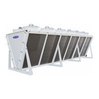
The Carrier 09VE Drycooler is a device designed to cool a fluid in a liquid state through heat exchange with ambient air, without direct contact between the air and the fluid. It can also be equipped with a misting option for air cooling using high-pressure water droplets. These units are intended for specific purposes, and the use of any fluid other than that specified in the order documents is strictly prohibited.
Important Technical Specifications
The drycooler units are designed to meet EN 60-204 standards and comply with European directives including Machinery 2006/42/EU, EMC 2014/30/EU, and PED 2014/68/EU.
Key specifications from the nameplate include:
- Item Ref.: e.g., 7225488.362873
- Year of manufacture: e.g., 2015
- Serial Nbr: e.g., 022777238/0001
- PED 2014/68/UE (DN): Category and determining value (e.g., ART4.3-LIQ-GR2 (DN: 100))
- Fluid CIRC. 1 & 2: EAU (Water)
- Volume: 311 L
- P.serv./working P (PS): 1.00 (13.0) BARS (Operating pressure)
- Max. temperature: 110 °C
- Voltage: TRI 400 50HZ
- P. abs \ P. input: 47600 W
- Current (+/-10%): 70.4 A
- Poids-Weight: 3930 KG (Empty weight including options and accessories)
Designation Breakdown (e.g., 1 10 4 UI 740 E 8A 12A1):
- 10: Number of fans
- 4: Number of rows of finned tubes (3 or 4)
- 740: Rotation speed (rpm)
- E: Motor type (A=AC 3-ph/400V/50Hz, B=AC other voltages, E=EC motors, X=ATEX motors, M=1 stage with EC motors)
- 8A: Motor impeller (9A/9B/9C/9D = Ø 910 mm, 8A/8B/8C/8D = Ø 800 mm)
- 12A1: Type of fins (12A1 = Ø 12.7 mm, 16B2 = Ø 16/15.87 mm)
AC Fan Motor Assemblies (3-ph 230 V/400 V 50 Hz):
- Impeller diameter: 910 mm or 800 mm
- Motor types: A9A, A9B, A9C, A9D (for 910 mm); A8A, A8B, A8C (for 800 mm)
- Supply: 3-PH/230 V (Δ connection), 3-PH/400 V (Y or Δ connection)
- Speed(s) rpm: Ranges from 300 to 1280 rpm depending on motor type and connection
- Weight of impeller + motor: 19-28 kg
- Weight of fan motor assembly: 38-70 kg
- Min. room/operating temperature: -40 °C
- Insulation class: F
- Sealing class: IP 54
- Number of starts: Max. 50/hour
AC Fan Motor Assemblies (3-ph 208 V and 3-ph/400 V to 480 V 60 Hz):
- Impeller diameter: 910 mm or 800 mm
- Motor types: B9A, B9B, B9C (for 910 mm); B8A, B8B, B8C, B8D (for 800 mm)
- Supply: 3-ph 208 V/60 Hz (Δ connection), 3-ph/400 to 480 V/60 Hz (Y connection)
- Speed(s) rpm: Ranges from 520 to 1100 rpm
- Weight of impeller + motor: 19-28 kg
- Weight of fan motor assembly: 47-69 kg
- Min. room/operating temperature: -40 °C
- Insulation class: F
- Sealing class: IP 54
- Number of starts: Max. 50/hour
EC Fan Motor Assemblies (3-ph 380 V to 480 V 50/60 Hz):
- Impeller diameter: 910 mm or 800 mm
- Supply voltage: 3-PH/380 - 480 V/50/60 Hz
- Control signal: 0/10 V or 4/20 mA
- Motor types: E9A, E9B (for 910 mm); E8A, E8B, E8C (for 800 mm)
- Max. speed(s) rpm: 510 to 1100 rpm
- Weight of impeller + motor: 9-25 kg
- Weight of fan motor assembly: 26-65 kg
- Min. room temperature for storage: -40 °C
- Min. operating temperature: -25 °C to -40 °C
- Insulation class: F
- Sealing class: IP 54
- Number of starts: Max. 50/hour
Usage Features
- Installation: Units must be installed outdoors in a flood-protected area, considering negative outdoor temperatures, corrosive atmospheres, and altitude. The ground surface must be level and strong enough to bear the unit's weight. Raising the unit is recommended in snowy areas for sufficient air intake. Protection against sandstorms and avoiding proximity to deciduous trees are advised. The maximum permitted wind speed once secured to the floor is 100 Km/h. For higher speeds, contact Carrier.
- Electrical Connection: All wiring must comply with local regulations (e.g., NF C 15100 in France). Refer to the "ELECTRICAL CONNECTION" document or wiring diagram. Phase unbalance must not exceed ±2% for voltage. Motors are partitioned in pairs for units without wiring or with an electrics box option. Protection against mains voltage spikes and lightning is crucial.
- Fluid Connection: Prevent foreign bodies from entering the circuit. Connection pipes and regulation equipment must be supported to avoid exerting force on the coil piping. Flexible connectors are recommended to prevent water hammer.
- Speed Regulator: A specialist must commission the regulator. Use shielded cables, set frequency between 25 and 50 Hz, and fit a DU/DT filter between the regulator and fans.
- First Commissioning: Verify supply voltage, retighten electrical connections, and check fan rotation direction. Ensure hydraulic circuits are clean and bleed air from the system during charging.
- Operation Recommendations: Use only treated water or authorized fluids to prevent scaling and corrosion, which negatively affect operation and service life.
- Control Cabinet with Electronic Board Option: Protects and controls motors, monitors operating parameters, communicates with chillers and remote consoles, diagnoses faults. Includes a padlockable front disconnect switch, thermal-magnetic circuit breakers, and a fluid temperature sensor. Outdoor temperature sensor placement is critical: on the building's closest northern side, away from moving air, protected from direct sunlight.
- Control Cabinet Controlled by Chiller Option (AUX1): Similar to the electronic board option but specifically designed for communication with chillers that have the board embedded.
- Electrics Box Option: Centralizes wiring and fans at the front of the unit. Includes 3-stage terminals for phase connection, thermal cut-out connection, and 0/10 V signal for EC FMA.
Maintenance Features
- Safety Precautions: Always disconnect power before servicing. Reduce temperature and pressure before working on the bundle. Do not modify the unit without agreement. Avoid walking directly on the unit.
- Freezing Protection: For units using water without anti-freeze, drain the circuit using bleed nozzles and vents, circulate compressed air to remove all water, then fill with anti-freeze and close the circuit.
- Winter Care: Prevent snow accumulation around and on top of the unit.
- Coatings: Periodically check coating condition and apply touch-ups.
- Maintenance Frequency:
- 6 months: Retighten nuts and bolts on fan motor assemblies, packing boxes, and terminal box mounting bolts.
- 1 year (or 1 month after system start-up then 1 year): Clean the coil, retighten electrical connections, retighten all visible nuts and bolts, check for corrosion on panelling and presence of safety labels/name plate.
- 5 years: Check electrical cables.
- Cleaning Coils:
- Switch off the unit.
- Remove protective screen if present.
- Straighten damaged fins with a comb.
- Minor fouling: Use dry air up to 30 bar (counter-flow). Periodically reversing fan air flow can prevent this (not possible with EC motors).
- Moderate fouling: Use a high-pressure (HP) steam cleaner with a flat jet nozzle (25°). Max pressure 100 bar, steam max 140°C, min distance 200 mm. Use municipal water with pH neutral detergent (pH 7). Avoid alkaline detergents. Flush with clean water.
- Important: Do not use detergent on BLYGOLD®, ALTENA®, or HERESITE® coated fins.
- Fan Removal/Refitting:
- For A9A, A9C, A8A, A8B, E9A, E8A, E8B, M9, M8, B9A, B9B, B9C, B8A, B8B, B8C and B8D: Disconnect power, remove terminal box cover, disconnect wires, loosen cable glands, remove clamps, remove 4 M8 bolts (T40 torx spanner), and lift fan using lifting lugs. Do not unscrew motor mounting bolts.
- For A9B, A9D, A8C, E9B and E8C: Disconnect power, remove fan protective grille, remove terminal box cover, disconnect wires, loosen cable glands, remove clamps, remove 12 bolts, and lift fan using hooks in ø12 mm holes.
- Refitting: Position fan on inserts, use M8x25 bolts (12 Nm torque) for V units or M10x25 bolts (24 Nm torque) for flatbed units. Ensure blades do not touch collar, wiring is correct, terminal box seal is in place, and bolts are tightened (2.5 Nm for ECs, 1.3 Nm for ACs).
- ATEX Areas (Special Information):
- General: Units are certified for ATEX zones. Installation and commissioning by qualified professionals. Ensure unit temperatures remain within -40 to +60°C. All metal elements must be grounded. Heat protection for motors is compulsory.
- Periodic Inspections/Checks:
- Unit Vibration: Check for wear, imbalance, and dust accumulation. Frequency: every 150 hours (or weekly) for the first month, then every 2000 hours (or every 3 months). If alarm level reached, schedule 2nd inspection. If max thresholds exceeded, stop fan, record, and perform 2nd inspection.
- Ground Continuity: Check ground straps visually and measure resistance (must not exceed 25% of reference). Frequency: every 150 hours (or weekly) for the first month, then every 5000 hours (or annually). If resistance check fails, clean or replace ground strap.
- Tools in Explosive Atmosphere: Only Type A tools (single sparks) are permitted in zones 1 and 2. Type B tools (plume of sparks) only if no dangerous explosive atmosphere is present. Use of steel tools in zone 1 with IIC substances is prohibited unless safety is assured. All tool use must be subject to a "work permit" system.
- Destruction of the Unit: Separate from energy sources, cool, and drain completely. Disassembly by qualified personnel using PPE. Sort components for recycling (galvanized carbon steel, stainless steel, copper, aluminum, plastics, polyurethane foam, electrical equipment). Recover fluids (MEG, MPG, thermal fluid, refrigerants, compressor oil). Follow WEEE directives for electrical and electronic equipment disposal.