EasyManua.ls Logo

Carrier COMFORTLINK 48A2 - User Manual

Carrier COMFORTLINK 48A2
8 pages
Print Icon
To Next Page IconTo Next Page
Loading...
Manufacturer reserves the right to discontinue, or change at any time, specifications or designs without notice and without incurring obligations.
Catalog No. 04-53480052-01 Printed in U.S.A. Form 48A-5SO Pg 1 3-08 Replaces: 48A-3SO
Book 1
Ta b 1 a
User’s Information Manual
NOTE TO INSTALLER
This manual should be left with the equipment owner.
Your combination heating/cooling unit is equipped with
direct spark ignition and induced draft power combustion
blower.
TO LIGHT UNIT
See Fig. 1 and 2 for location of gas valve. Refer to Fig. 3
while performing the following steps.
1. Disable unit operation by using the scrolling marquee.
The scrolling marquee is located in the control box at the
compressor end of the unit.
a. Push the key unit a blank display screen
is shown.
b. Push the key until the SERVICE TEST LED is
lit.
c. Push the key. The display will show
STOP.
NOTE: Items in the Configuration and Service
Test modes are password protected. The display
will flash PASS and WORD when required. Use
the and arrow keys to enter the 4 digits of
the password. The default password is 1111.
d. Push the key again. The NO/YES display
will flash.
e. Push the or key to toggle the display to
YES and then push . The unit will be
locked off from heating, cooling or any operation.
The controls will still function and the display will
still operate.
2. Close the field-installed manual gas shutoff valve.
3. Turn off the electrical power to the unit using the optional
disconnect or the field-installed disconnect and lock off
using proper lockout and tag-out procedures.
4. Remove the gas section panels.
5. Move the switch on the gas valve to the OFF position and
wait 5 minutes.
NOTE: If this is the first installation of the unit, the gas
flue hoods must be installed before operating unit. These
must be installed for the unit to run properly.
WARNING: If the information in this
manual is not followed exactly, a fire or
explosion may result causing property
damage, personal injury or loss of life.
Do not store or use gasoline or other
flammable vapors and liquids in the
vicinity of this or any other appliance.
WHAT TO DO IF YOU SMELL GAS
Do not try to light any appliance.
Do not touch any electrical switch;
do not use any phone in your
building.
Immediately call your gas supplier
from a neighbor’s phone. Follow the
gas supplier’s instructions.
If you cannot reach your gas sup-
plier, call the fire department.
Installation and service must be per-
formed by a qualified installer, service
agency or the gas supplier.
WARNING
Improper installation, adjustment, alteration, ser-
vice or maintenance can cause injury or property
damage. Refer to this manual. For assistance or
additional information consult a qualified installer,
service agency, or the gas supplier.
WARNING
Before performing recommended maintenance, be sure
main power switch to unit is turned off and lockout tag is
installed. Electrical shock could cause personal injury.
WARNING
Burners will light automatically. Do not attempt to light by
hand; personal injury may result.
DANGER
1. Do not turn off the electrical power to unit without
first turning off the gas supply.
2. Before attempting to start the gas heating section,
familiarize yourself with all the procedures that must
be followed.
3. Never attempt to manually light the burners on the
unit with a match, lighter, or any other flame. If the
electric sparking device fails to light the burners, refer
to the shutdown procedures, then call your dealer as
soon as possible.
If you do not follow these instructions exactly, a fire or
explosion may result, causing property damage, injury, or
loss of life.
ESCAPE
ENTER
ENTER
ENTER
ENTER
48A2,A3,A4,A5020-060
Single-Package Rooftop
Gas Heating/Electric Cooling Units
with COMFORTLINK™ Controls and Scroll Compressors
Question and Answer IconNeed help?

Do you have a question about the Carrier COMFORTLINK 48A2 and is the answer not in the manual?

Summary

Installer Notes and Warnings

Installer Safety Precautions

Crucial safety alerts for installers regarding fire, explosion, and electrical hazards.

Gas Leak Response Procedure

Procedure to follow if a gas leak is detected, emphasizing immediate action and professional contact.

Lighting the Unit

DANGER: Lighting Hazards

Highlights severe risks, including fire and explosion, associated with improper lighting procedures.

Lighting Unit Steps (1-5)

First five steps for lighting the unit, involving unit disabling and gas valve operation.

Lighting Unit Steps (6-12)

Continuation of steps for safely lighting the unit, including valve and control adjustments.

Shutting Down the Unit

Shutdown Safety Warnings

Critical warnings before shutting down the unit, emphasizing gas supply first.

Overview

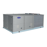
This document is the User's Information Manual for the Carrier 48A2, A3, A4, A5020-060 Single-Package Rooftop Gas Heating/Electric Cooling Units, featuring COMFORTLINK™ Controls and Scroll Compressors. It provides essential information for both installers and equipment owners regarding the safe and efficient operation and maintenance of these units.

Function Description

The Carrier 48A2, A3, A4, A5020-060 units are single-package rooftop systems designed to provide both gas heating and electric cooling. They are equipped with COMFORTLINK™ controls, which offer advanced management and diagnostic capabilities, and utilize scroll compressors for efficient refrigeration. The gas heating section employs direct spark ignition and an induced draft power combustion blower, ensuring automatic burner lighting. The units are designed for rooftop installation, providing a compact and integrated solution for climate control in commercial or industrial settings.

Usage Features

The manual emphasizes safety and proper operating procedures. A critical section details the "TO LIGHT UNIT" procedure, which must be followed precisely to avoid fire or explosion hazards. This involves disabling unit operation via the scrolling marquee on the control box, closing the field-installed manual gas shutoff valve, turning off electrical power, removing gas section panels, and moving the gas valve switch to the OFF position for 5 minutes before attempting to restart. The COMFORTLINK™ controls feature a scrolling marquee with various modes (Run Status, Service Test, Temperature, Pressures, Setpoints, Inputs, Outputs, Configuration, Time Clock, Operating Modes, Alarms) and navigation keys (ESCAPE, ENTER, arrow keys). To light the unit, users must navigate through the Service Test mode, enter a password (default 1111), and enable the unit to run. The system is designed for automatic burner lighting, and manual ignition with a match or lighter is strictly prohibited. For normal operation, it's crucial to ensure that conventional thermostats are set to the correct heating control temperature, or that space temperature sensors in VAV (variable air volume) and CV (constant volume) units have appropriate heat set points.

The manual also outlines the "TO SHUT UNIT OFF" procedure, which mirrors the lighting steps in reverse, starting with disabling unit operation via the scrolling marquee, closing the manual gas shutoff valve, turning off electrical power, removing gas section panels, and moving the gas valve switch to OFF. This shutdown procedure is particularly important if the main burners fail to light, the blower fails to start, or if there is a malfunction requiring service. The COMFORTLINK™ controls allow the unit to be locked off from heating, cooling, or any operation while still maintaining control functionality and display operation.

Maintenance Features

The manual stresses that all maintenance should be performed by skilled, experienced personnel, and recommends consulting a qualified installer, service agency, or gas supplier for assistance. It provides a comprehensive list of routine maintenance and care items for the equipment owner, with strong warnings about safety precautions.

Key maintenance aspects include:

  • Air Filter(s): Filters (2-inch or 4-inch thick) should be checked monthly and changed as necessary. The filter access panel is located at the end of the unit opposite the condenser section. The manual provides detailed steps for inspecting and replacing filters, including loosening latches, removing panels, sliding retainers, and using a filter removal rod for hard-to-reach filters. It explicitly warns against operating the unit without filters, as this can damage the blower motor and/or compressor, reduce efficiency, and pose a fire risk. Units with outdoor air capability have cleanable filters that should be checked annually and cleaned with steam, hot water, and a mild detergent.
  • Heat Exchanger: To ensure dependable and efficient heating, the heat exchanger should be checked by a qualified maintenance person before each heating season and cleaned as necessary. This involves removing gas controls, the flue collector box, and its cover, and should only be done by those with the necessary expertise and equipment.
  • Fans and Belts: The condition of fan wheels, housings, and belt tension should be checked periodically, with service handled by a dealer.
  • Indoor-Fan Motor, Outdoor-Fan Motor, and Combustion Fan Motor: Lubrication is generally not required for at least 5 years; after this period, motors may need servicing by an authorized motor service shop.
  • Fan Shaft Bearings: These should be greased annually with Shell Alvania no. 2 grease or equivalent, but not more than once a year.
  • Evaporator and Condenser Coils: Cleaning of coils should be done by qualified service personnel annually.
  • Condensate Drain: The drain pan and condensate drain line should be checked and cleaned when the cooling coils are serviced.
  • Compressor: Compressors are factory-supplied with the correct type and charge of refrigeration-grade oil and do not require additional oil.
  • Condenser Fan: Users are warned not to poke objects into revolving fan blades due to severe bodily injury risk. The fan must be kept free of obstructions for proper cooling.
  • Electrical Controls and Wiring: These are difficult to check without proper instrumentation; any discrepancies in the operating cycle should prompt a service call.
  • Refrigerant Circuit: Checking for leaks requires specialized equipment; inadequate cooling should lead to a service call.
  • Combustion Area and Vent System: A visual inspection of the combustion area and vent system is recommended before each heating season to check for dirt, soot, rust, or scale, which can lead to efficiency loss and improper performance. If such accumulations are found, the heating section should not be operated, and a dealer should be called.

The manual also includes a "BEFORE YOU CALL FOR SERVICE, CHECK FOR PROBLEMS THAT CAN BE EASILY SOLVED" section, which guides users through basic troubleshooting steps such as checking airflow, thermostat settings, electrical supply, and gas valve positions. It advises recording the unit's model and serial numbers for quicker service.

Crucially, the manual includes multiple "WARNING" and "CAUTION" advisories throughout, highlighting potential hazards such as fire, explosion, personal injury from hot components, electrical shock, sharp sheet metal, and operating without filters. It also provides instructions for what to do if the unit has been submerged in water, emphasizing the need for a qualified service technician to inspect and replace affected parts. The document concludes by recommending regular dealer maintenance, including a comprehensive list of inspections to be performed by a properly trained service technician, ideally annually or every other year.

Carrier COMFORTLINK 48A2 Specifications

General IconGeneral
BrandCarrier
ModelCOMFORTLINK 48A2
CategoryFreezer
Voltage208-230V
Phase1
Frequency60 Hz
Capacity48 cu. ft.
RefrigerantR404A
Defrost TypeElectric

Related product manuals