EasyManua.ls Logo

Carrier 50DP020 - User Manual

Carrier 50DP020
16 pages
Print Icon
To Next Page IconTo Next Page
Loading...
HEATING
&
COOLING
50DPE014
50DP016,020
Single-Package
Cooling
Units
Installation,
Start-Up
and
Service
Instructions
CONTENTS
Page
SAFETY
CONSIDERATIONS.
!
INSTALLATION
.1-10
Step
1
Provide
Unit
Support.
1
ROOF
CURB
ALTERNATE
UNIT
SUPPORT
Step
2
Rig
and
Place
Unit.
I
POSITIONING
ROOF
MOUNT
Step
3
Field
Fabricate
Ductwork.6
Step
4
Make
Unit
Duct
Connections.6
Step
5
Trap
Condensate
Drain
.6
Step
6
Make
Electrical
Connections.7
FIELD
POWER
SUPPLY
FIELD
CONTROL
WIRING
Step
7
Make
Outdoor
Air
Inlet
Adjustments.7
MANUAL
OUTDOOR
AIR
DAMPER
OPTIONAL
ECONOMIZER
Step
8
Install
Outdoor
Air
Hood.
10
START-UP.10-13
SERVICE.14-16
SAFETY
CONSIDERATIONS
Installation
and
servicing
of
air
conditioning
equip¬
ment
can
be
hazardous
due
to
system
pressure
and
elec¬
trical
components.
Only
trained
and
qualified
service
personnel
should
install,
repair
or
service
air
conditioning
equipment.
Untrained
personnel
can
perform
basic
maintenance
functions
of
cleaning
coils
and
filters
and
replacing
filters.
All
other
operations
should
be
performed
by
trained
service
personnel.
When
working
on
air
condi¬
tioning
equipment,
observe
precautions
in
the
literature,
tags
and
labels
attached
to
the
unit
and
other
safety
pre¬
cautions
that
may
apply.
Follow
all
safety
codes.
Wear
safety
glasses
and
work
gloves.
Use
quenching
cloth
for
unbrazing
operations.
Have
fire
extinguishers
available
for
all
brazing
operations.
A
WARNING
,
Before
performing
service
or
maintenance
operations
on
unit,
turn
off
main
power
switch
to
unit.
Electrical
shock
could
cause
personal
injury.
INSTALLATION
Step
1
Provide
Unit
Support
ROOF
CURB
Assemble
and
install
accessory
roof
curb
in
accordance
with
instructions
shipped
with
this
accessory.
Accessory
roof
curb
and
information
required
to
field
fabricate
a
roof
curb
are
shown
in
Fig.
1
and
2.
Install
insulation,
cant
strips,
roofing
and
flashing
as
shown.
Ductwork
can
be
installed
to
roof
curb
before
unit
is
set
in
place.
Curb
should
be
level.
Unit
leveling
toler¬
ance
is
±
1/16
in.
per
linear
ft
in
any
direction.
This
is
necessary
to
permit
unit
drain
to
function
properly.
Refer
to
Accessory
Roof
Curb
Installation
Instructions
for
additional
information
as
required.
ALTERNATE
UNIT
SUPPORT
When
the
curb
cannot
be
used,
support
unit
with
sleepers
using
unit
curb
support
area.
If
sleepers
cannot
be
used,
support
long
sides
of
unit
with
a
minimum
of
3
equally
spaced
4-in.
x
4-in.
pads
on
each
side.
Step
2
Rig
and
Place
Unit
Inspect
unit
for
transportation
damage.
File
any
claim
with
transporta¬
tion
agency.
Do
not
drop
unit,
keep
upright.
Use
spreader
bars
over
unit
to
prevent
sling
or
cable
damage.
Rollers
may
be
used
to
move
unit
across
a
roof.
Level
by
using
unit
frame
as
a
reference;
leveling
tolerance
is
±
1/16
in.
per
linear
ft
in
any
direction.
See
Fig,
3
for
additional
information.
Unit
weight
is
shown
in
Table
1.
Four
lifting
holes
are
provided
in
ends
of
unit
base
rails
as
shown
in
Fig.
3.
Refer
to
rigging
instructions
on
unit.
POSITIONING
Provide
clearance
around
and
above
unit
for
airflow,
safety
and
service
access
(Fig.
4).
Manufacturer
reserves
the
right
to
discontinue,
or
change
at
any
time,
specifications
or
designs
without
notice
and
without
incurring
obligations.
Bookll
|4
PC111
Catalog
No
565-104
PrintedinUSA
Form
50DP-26SI
Pg
1
7-88
Replaces:
50DP-25SI
Tab
|lb|6b
Question and Answer IconNeed help?

Do you have a question about the Carrier 50DP020 and is the answer not in the manual?

Summary

Safety Considerations for Installation

General Installation Safety Precautions

General safety precautions for installing air conditioning equipment, emphasizing trained personnel.

Electrical Shock Warning

Warning to turn off main power before service to prevent electrical shock.

Installation Steps

Provide Unit Support and Rigging

Procedures for providing unit support and rigging, including curbs, weights, and positioning.

Ductwork, Electrical, and Air Inlet Connections

Steps for ductwork fabrication, unit connections, electrical wiring, and air inlet adjustments.

Outdoor Air Hood Installation

Procedure for assembling and installing the outdoor air hood components.

Start-Up Procedures

Unit Preparation and Compressor Checks

Checks before start-up including unit prep, compressor mounting, and internal wiring.

Refrigerant Valves and Crankcase Heaters

Ensuring refrigerant valves are open and understanding crankcase heater operation.

Heat Anticipator Settings

Table of heat anticipator settings for different unit models and voltages.

Service and Maintenance

Cleaning and Lubrication Guidelines

Procedures for cleaning unit components and compressor lubrication.

Fan Adjustment Procedures

Steps for adjusting indoor and outdoor fan speeds and belt tension.

Overview

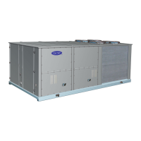
This document describes the installation, start-up, and service procedures for Carrier 50DPE014, 50DP016, and 50DP020 Single-Package Cooling Units.

Function Description:

These units are single-package cooling units designed for commercial and industrial applications. They are capable of providing cooling, heating (with optional electric heat), and ventilation air circulation. Some models are equipped with economizers for modulating outdoor air control, allowing for "free cooling" when outdoor air conditions are favorable. Certain units also feature variable volume air handling systems with electric unloaders on the compressor, controlled by a step controller, proportional thermostat, and 7-day timer to maintain desired temperatures and optimize energy usage.

Important Technical Specifications:

The units come in various sizes (50DPE014, 50DP016, 50DP020) with different operating weights, refrigerant charges, and electrical configurations.

  • Refrigerant: R-22, with charges varying by system (e.g., 20.8 lb for 50DPE014, 21.2 lb for 50DP016, 17.0 lb for 50DP020).
  • Compressor: Semi-hermetic, 6 cylinders. 50DPE014 and 50DP016 have 1 compressor, while 50DP020 has 2.
  • Refrigerant Metering Device: Capillary tubes, with varying quantities and dimensions depending on the unit and circuit (upper/lower).
  • Outdoor Coil: Copper tube, aluminum or copper plate fins, with 3 or 4 rows.
  • Outdoor Air Fan: Propeller type, direct drive, with nominal Cfms ranging from 11,400 to 12,000.
  • Indoor Coil: Copper tube, aluminum or copper plate fins, with 3 or 4 rows.
  • Indoor Air Fan: Centrifugal, belt drive. Sizes vary (e.g., 2-10x10 for 50DPE014/50DP016, 2-12x12 for 50DP020). Nominal Cfms range from 5000 to 7200. Some units (50DPE014, 50DP016) have adjustable standard and alternate drives, while 50DP020 has fixed pulleys.
  • High-Pressure Switch: Cutout at 428 psig, reset at 320 psig.
  • Low-Pressure Switch (Liquid Line): Cutout at 27 psig, reset at 60 psig.
  • Air Inlet Screens: Economizer models include 20x25x1 or 20x20x1 screens.
  • Indoor Air Filters: 10% efficient disposable fiberglass filters, with various sizes and quantities (e.g., 2x20x20x2, 3x16x20x2, 2x16x25x2 for 50DPE014).
  • Electrical Data: Units are available in 208/230-3-60, 460-3-60, and 575-3-60 voltage configurations. Minimum Circuit Amps (MCA) and Maximum Overcurrent Protection (MOCP) values are provided for each model and voltage.
  • Air Quantity Limits: Minimum and maximum CFM values are specified for each unit model (e.g., 3750-6250 CFM for 50DPE014, 5400-9000 CFM for 50DP020).

Usage Features:

  • Installation: Units can be supported by an accessory roof curb or alternate unit supports (sleepers or pads). Proper leveling (±1/16 in. per linear ft) is crucial for drain function. Ductwork can be connected through-the-bottom or concentrically.
  • Condensate Drain: Requires a 3/4-in. connection and a trap at least 4 in. deep, protected against freeze-up.
  • Electrical Connections: Field power supply and control wiring must comply with NEC and local codes. Voltage imbalance should not exceed 2% to avoid damage and warranty invalidation.
  • Outdoor Air Inlet: Manual outdoor air dampers allow for up to 25% ventilation air. Optional economizers provide modulating outdoor air control based on enthalpy settings.
  • Start-Up: Requires checking all installations, ensuring compressor hold-down bolts are secure, electrical connections are tight, and refrigerant service valves are open. Crankcase heaters must be energized for 24 hours prior to start-up.
  • Operating Modes: Supports Cooling, Heating (with electric heat), Continuous Fan, and Automatic Changeover.
  • Head Pressure Control: Fan cycling thermostats shut off one outdoor fan motor at 55°F, allowing operation down to 40°F outdoor air.
  • Economizer Operation: In cooling mode, the economizer damper modulates based on outdoor air enthalpy and mixed air thermostat settings. A freeze protection thermostat (FPT) prevents ice buildup on the indoor coil.
  • Variable Volume Units: These units feature a step controller with a 7-day timer and proportional thermostat for precise temperature control and compressor unloading. The 7-day timer allows for scheduled ON/OFF times.

Maintenance Features:

  • General Cleaning: Inspect unit interior at the start of each heating and cooling season. Remove top and side panels for access.
  • Coil Cleaning: Indoor coils should be cleaned with a commercial coil cleaner. Outdoor coils should be cleaned annually or as required, and inspected monthly.
  • Condensate Drains: Check and clean annually at the start of the cooling season. Keep drains and traps dry in winter.
  • Filters: Replace or clean indoor air filters at the start of each heating and cooling season, or more often as needed. Outdoor air inlet screens should be cleaned with steam or hot water and mild detergent.
  • Lubrication: Compressors are factory-charged with oil. Fan shaft bearings are permanently lubricated. Fan motor bearings and indoor blower motors require cleaning and repacking with suitable grease annually after the first 5 years.
  • Fan Adjustment: Indoor air fan speed can be adjusted by manipulating the movable pulley flange (for 50DPE014 and 50DP016). Belt tension should be checked and adjusted. Outdoor air fan height can be adjusted by loosening hub screws.
  • Refrigerant Charge: Refer to unit nameplate and charging charts (Fig. 24, 25) for correct refrigerant amounts. Charging procedures involve evacuating the system and weighing in the specified amount, or adding refrigerant based on suction pressure and temperature readings.
  • Economizer Adjustment: Involves setting enthalpy control, mixed air thermostat, and adjusting mechanical linkage for correct damper positioning.
  • 50DP020 Indoor Air Fan Motor Removal: Detailed steps are provided for removing the motor and pulley assembly for maintenance.

Carrier 50DP020 Specifications

General IconGeneral
BrandCarrier
Model50DP020
CategoryFreezer
LanguageEnglish

Related product manuals