4
a48---10366
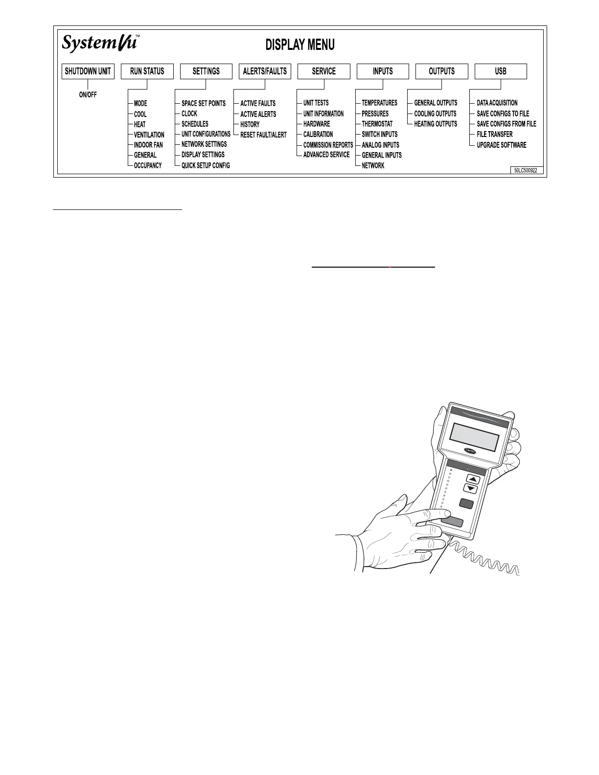
Fig. 2 -- SystemVut -- Main Menu Structures
SystemVu Interface Operation
Units are shipped from the factory with the SystemVu interface
FIOP, located in the main control box. (See Fig. 1.) In addition, the
interface has up and down arrow keys, BACK, ENTER, MENU,
and TEST keys. These keys are used to navigate through the
different levels of the menu structure. All discussions and examples
in this document will be based on the SystemVu display except in
the Navigatort display section. See the Accessory Navigator
Display section for further details and Table 2 for the Navigator
menu structure and usage.
The six keys are used to navigate through the display structure,
which is organized in a tiered menu structure. If the buttons have
not been used for a period, the display will default to a standby
screen intended to provide a quick overall look at the system. To
show the top --level display, press any key first to turn the display
backlight on, and then press the MENU key. Then use the up and
down arrow keys to scroll through the top --level menus. These are
showninFig.2andlistedinAppendixA.
When a specific menu or sub--menu is located, push the ENTER
key to enter the menu. Depending on the menu, there may be
additional tiers. Continue to use the up and down keys and the
ENTER key until the desired display item is found. At any time,
the user can move back a menu level by pressing the BACK key .
Once an item has been selected the display will flash showing the
item, followed by the item value and then followed by the item
units (if any). Pressing the TEST button at any time will jump the
display to the test menu. Pressing the MENU button any time will
jump the display to the main menu.
Items in the Configuration and Service Test menus are password
protected. The display will prompt the enter password screen when
required. Use the ENTER, BACK, and arrow keys to enter the four
digits of the password. The default user password is 1111.
Pressing the BACK and ENTER keys simultaneously will show an
expanded text description screen on the display indicating the full
meaning of each display point. T o put the screen in standby, hold
down the BACK key for 5 seconds.
Some point s can be forced fr om the Syst emVut interface. To force a
variable, follow the same process as editing a configuration
parameter. A forced variable, regardless where the force has come
from will be displayed with a lower case “f” following its value.
For example, if ECON CMD POSITION is forced, the display
shows “80%f”, where the “f” is to signify a force on the point.
Remove the force by selecting the point that is forced with the key
ENTER and then p ressing the up and down arrow keys
simultaneously . Pressing ENTER and BACK on a forced item will
display the expanded description for that item including the force
level that is currently applied. Depending on the type of unit
(48FC,GC or 50FC,GC), factory --installed options and
field--installed accessories, some of the items in the various menus
may not apply.
Accessory Navigatort Display
The accessory hand-held Navigator display can be used with the
48/50FG, GC units. (See Fig. 3.) The Navigator display is plugged
into the LEN (local equipment network) port on either the
SystemVu disp lay or the Main Base Board (MBB).
Navigator Display Operation
The Navigator display has up and down arrow keys, an ESCAPE
key and an ENTER key. These keys are used to navigate through
the different levels of the display structure.
The four keys are used to navigate through the display structure,
which is organized in a tiered mode structure. If the buttons have
not been used for a period, the display will default to the AUTO
VIEW display category as shown under the RUN STATUS
category. To show the top-level display, press the ESCAPE key
until a blank display is shown. Then use the up and down arrow
keys to scroll through the top-level categories. These are listed in
Appendix C and will be indicated on the Navigator display by the
LED next to each mode listed on the face of the display.
Ru
n Sta
tu
s
S
e
rv
ice
Te
s
t
T
em
p
era
ture
s
P
res
s
ure
s
S
e
tpo
in
ts
In
pu
ts
O
utp
uts
C
on
fig
u
ra
tion
T
im
e C
lo
ck
O
p
er
ating
Mod
es
A
la
rm
s
E
N
T
E
R
E
S
C
M
O
D
E
Ala
rm
Sta
tus
T
IM
E
E
W
T
L
W
T
S
E
T
P
1
2
.
5
8
5
4
.
6
°
F
4
4
.1
°
F
4
4
.
0
°
F
N
A
V
I
G
A
T
O
R
C
o
m
f
o
r
t
L
in
k
C06321
Fig. 3 -- Accessory Navigator Display
Whe n a specific mode or sub-mode is located, push the ENTER key
to enter the mode . Depending on the mode, the re may be additional
tiers. Cont inue to us e the up a nd down keys and the ENTER keys
until the desired display item is f ound. At any time, the user can move
back a mode level by pre ssing the ESCAPE key. Onc e an ite m has
been selected the display will flash showing the item, followed by the
item value and then followed by the item units (if any).
Items in the Configuration and Service Test modes are password
protected. The display will flash PASS and WORD when required.
Use the ENTER and arrow keys to enter the four digits of the
password. The default password is 1111.

 Loading...


