EasyManua.ls Logo

Carrier 50FC Series User Manual

Carrier 50FC Series
144 pages
To Next Page IconTo Next Page
Page #1 background imageLoading...
Page #1 background image
1
Controls, Start-- Up, Operation
and Troubleshooting
48/50FC 04---07, 48/50GC 04---06
Single P ackage Rooft op Units
with SystemV u™ Controls Version 1.X
and Puronr (R---410A) Refr ig er ant
C150173
IMPORTANT: This literature covers 48/50FC 04--07 and 48/50GC 04--06 models with SystemVu controls version 1.X (factory--installed
option).
TABLE OF CONTENTS
Page
SAFETY CONSIDERATIONS 2.........................
GENERAL 3.........................................
Conventions Used in This Manual 3......................
BASIC CONTROL USAGE 3...........................
SystemVu Control (factory --installed option) 3..............
SystemVu Interface 3.................................
Accessory Navigatort Display 4........................
System Pilott andTouchPilott Devices 5................
CCN Tables and Display 5.............................
START -- UP 6.........................................
Unit Preparation 6....................................
Refrigerant Service Ports 6.............................
Crankcase Heater 6...................................
Compressor Rotation 6................................
Power Supply 6.....................................
Internal Wiring 6.....................................
Evaporator Fan 6....................................
Condenser Fans and Motors 6...........................
Return--Air Filters 8..................................
Outdoor--Air Inlet Screens 8............................
Accessory Installation 8...............................
Gas Heat (48FC and 48GC) 8...........................
CONTROLS QUICK SET-- UP 8.........................
Control Set Point and Confirmation Log 8.................
Initial Startup 8......................................
Thermostat Control 9.................................
Space T emperature Sensor Control -- Direct Wired
(T--55 or T--56 or T--59) 9.............................
Space Humidistat Control 9............................
Space Relative Humidity Sensor Control 9.................
CCN Communication 9...............................
CCN Linkage Control 9...............................
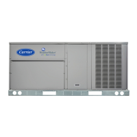
Table of Contents

Other manuals for Carrier 50FC Series

Question and Answer IconNeed help?

Do you have a question about the Carrier 50FC Series and is the answer not in the manual?

Carrier 50FC Series Specifications

General IconGeneral
BrandCarrier
Model50FC Series
CategoryAir Conditioner
LanguageEnglish

Summary

Controls, Start-Up, Operation and Troubleshooting

SAFETY CONSIDERATIONS

Essential safety precautions for installation and servicing of the equipment.

BASIC CONTROL USAGE

Explains the SystemVu control system and its interface for unit management.

START-UP

CONTROLS QUICK SET-UP

Initial Startup

Details the process for completing the initial startup prompt on the SystemVu controller.

Quick Setup

CCN Communication

Steps for configuring CCN communication settings.

Economizer

Configuration steps for a field-installed economizer.

SERVICE TEST

Cooling Test

Automatic Test

Describes the AUTOMATIC TEST submenu for executing system tests.

CONTROLS OPERATION

Unit Configuration

Describes configurations for factory options and accessories.

Configurable Switches and Analog sensors

General Operation

Demand Determination

Space Sensor Demand

Humidity Demand

Occupancy Determination

Indoor Fan Operation

Heating Operation

Heating Mode Control

Describes the three sub-modes of heating operation.

Supply Air Tempering

Two Position Damper Operation

Economizer Operation

Minimum Ventilation

Cooling Operation

Cooling Mode Control

Explains the nine operating sub-modes within the cooling HVAC mode.

Cooling Staging Control

Traditional Thermostat Control

Staging request based directly on thermostat inputs.

Compressor Control

Outdoor Fan Control

Low Ambient Operation

Operation with head pressure device when OAT is low.

Humidi--MiZerR Operation

Operation with head pressure device and reheat active.

Optional Humidi--MiZer Dehumidification System

Dehumidification Demand

How dehumidification demand is seen via switch input or sensor.

Humidi--MiZerR System Modes

Dehum/Mech Cooling (Subcooling) Mode

Increases latent heat removal and decreases sensible cooling.

Dehumidification (Hot Gas Reheat) Mode

Provides maximum latent cooling with minimal sensible capacity.

Reheat Control

Indoor Fan Based Dehumidification

Supply--Air Temperature Sensor (SAT) Heat Mode

Heating Staging Control

Adaptive Control

Stage timers and supply air trend determining stage requests.

Indoor Air Quality (IAQ)

Free Cooling

Unoccupied Free Cooling

Algorithm to maintain space temperature halfway between occupied set points using economizer.

Power Exhaust

Pre--occupancy Purge

Temperature Compensated Start

Linkage

Carrier Comfort NetworkR (CCN) Operation

BACnet Network Operation

Alarm Handling

Faults and Alerts

Information on viewing and clearing unit alarms.

Alarm Relay Output

Fault F011 – MBB REFERENCE VOLTAGE

Fault F018 – MBB EEPROM FAILURE

Alert A019 – MBB CLOCK FAILURE

Fault F020 – SOFTWARE ERROR

Alert A100 – SAT SENSOR FAILURE

Alert A104 – OAT SENSOR RANGE

Alert A107 – RAT SENSOR RANGE

Alert A110 – SPT SENSOR RANGE

Alert A130 – CIR.A SSP SENSOR RANGE

Alert A133 – CIR.A SDP SENSOR RANGE

Alert A160 – OARH OPEN SENSOR

Alert A162 – RARH OPEN SENSOR

Alert A164 -- IAQ OPEN SENSOR

Alert A166 -- OAQ OPEN SENSOR

Alert A168 -- SPACE RELATIVE HUMIDITY OPEN SENSOR

Alert A170 – ECON FEEDBACK RANGE

Alert A190 – TSTAT HEAT/COOL CALLS

Fault F200 – FIRE SHUTDOWN

Fault F201 – CONDENSATE OVERFLOW

Fault F318 – COMPRESSOR STUCK ON

Fault F319 – C.A1 DOWN DUE TO FAIL

Alert A320 – C.A1 REVERSE ROTATION

Alert A321 – C.A1 FAIL TO PRESSURE

Alert A410 – IGC IGNITION FAILURE

Fault F411 – ROLLOUT WITHOUT HEAT

Fault F412 – RUN AWAY HEAT

Alert A510 – INDOOR FAN STATUS

Fault F511 – IDF OFF WHEN COMMAND ON

Fault F512 – IDF ON WHEN COMMAND OFF

Alert A700 – ECON NOT MODULATING

Control Module Communication

Communication Failures

Cooling Troubleshooting

Humidi--MiZerR System Troubleshooting

Economizer Troubleshooting

Heating Troubleshooting

Gas Heat (48FC and 48GC Units)

Refers to Table 17 for general gas heating service analysis.

Electric Heat (50FC and 50GC Units)

Refers to Table 19 for electric heating service analysis.

Phase Protection

Thermistor Troubleshooting

Transducer Troubleshooting

MAJOR SYSTEM COMPONENTS

Main Base Board (MBB)

Integrated Gas Control (IGC) Board

Protective Devices

Compressor Protection

Details overcurrent and overtemperature protection for compressors.

Evaporator Fan Motor Protection

Protection for ECM motor against locked rotor and over-current.

Saturated Suction Pressure (SSP)

Monitors SSP for potential circuit shutdown and automatic reset.

Condensate Overflow Switch (COFS)

Detects full drain pan and controls relay switch.

Space Mounted Sensors

Space Temperature Sensor (T--55)

Details the T-55 sensor, its installation, and override button.

Space Temperature Sensor (T--56)

Details the T-56 sensor, its remote set point adjustment, and override button.

Carrier Comfort NetworkR (CCN) Interface

APPENDIX A: SystemVut Controller Display

Run Status Main Menu Layout

Details the layout of the Run Status main menu items.

Run Status Main Menu Layout (cont)

Continues the layout of the Run Status main menu items.

Settings Main Menu Layout

Details the layout of the Settings main menu items.

Settings Main Menu Layout (cont)

Continues the layout of the Settings main menu items.

Alerts/Faults Main Menu Layout

Details the layout of the Alerts/Faults main menu.

Service Main Menu Layout

Details the layout of the Service main menu.

Service Main Menu Layout (cont)

Continues the layout of the Service main menu.

Inputs Main Menu Layout

Details the layout of the Inputs main menu.

Inputs Main Menu Layout (cont)

Continues the layout of the Inputs main menu.

Outputs Main Menu Layout

Details the layout of the Outputs main menu.

APPENDIX B: SystemVu™ Controller Display

MODE - RUN STATUS

Lists items related to operating modes and run status.

MODE - SUB--MODE

Lists items related to operating sub-modes.

MODE - ALARMS

Lists items related to current alarms and alarm history.

APPENDIX C: Navigatort Display

MODE -- SERVICE TEST

Lists Navigator display items for service tests.

MODE -- ALARMS

Lists Navigator display items for alarms.

APPENDIX D: SystemVut Controller CCN Tables

Service Config Tables

Lists SystemVu controller service configuration tables.

Service Config Tables (cont)

Continues SystemVu controller service configuration tables.

APPENDIX E: BACnet Points List

UNIT START-UP CHECKLIST

I. PRE-START-UP:

Pre-start-up checks including packaging removal, installation verification, and connections.

II. START-UP

Start-up procedures focusing on electrical connections and measurements.

III. HUMIDI--MIZERR SYSTEM START-UP

Related product manuals