47
12 - FACTORY OPTIONS AND ACCESSORIES
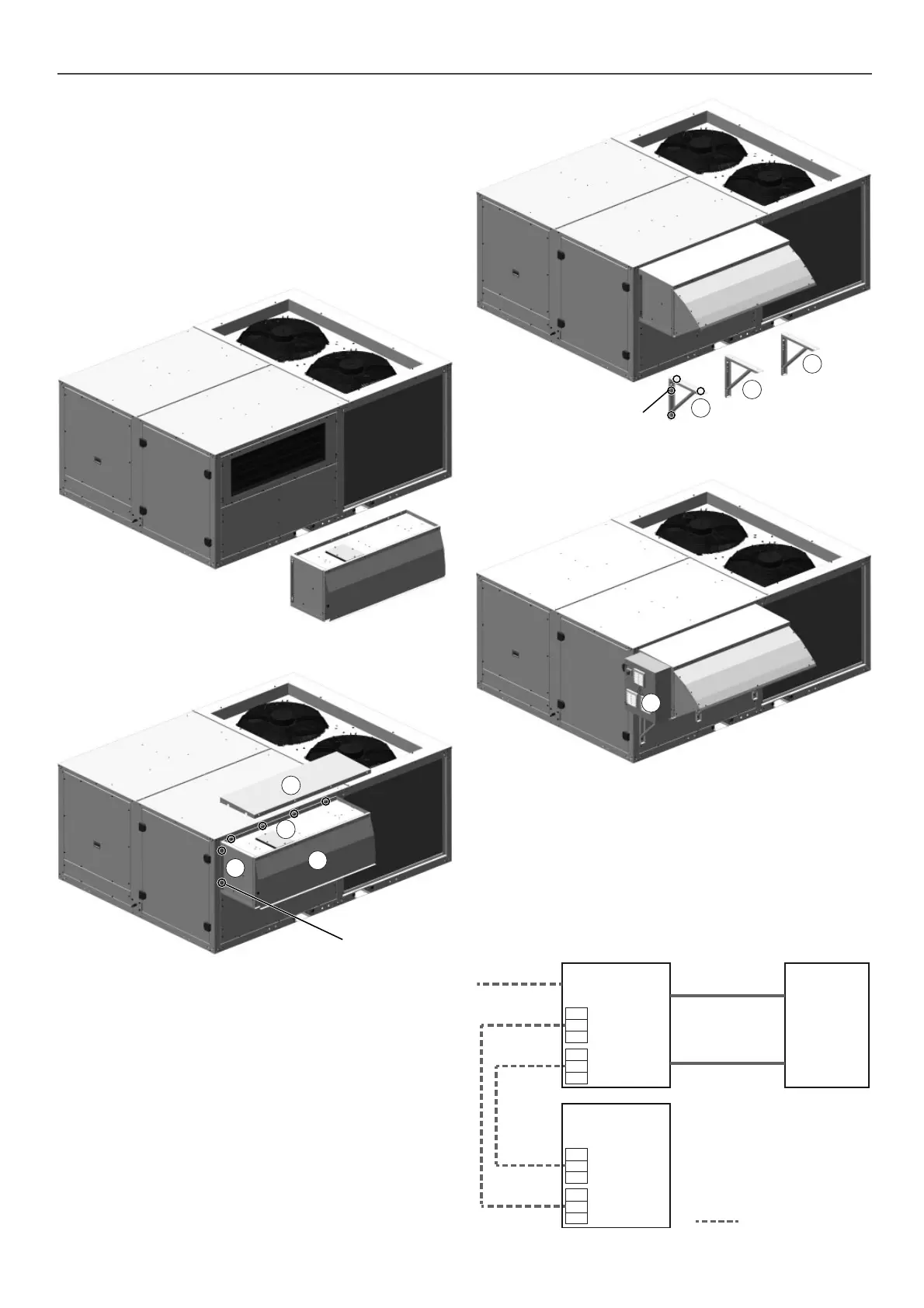
12.11 - Preheater module
With BF assembly, 100% fresh air, it is possible to incorporate a
preheater module (electrical heater) coupled to the fresh air intake.
This module is supplied in kit for installation on site.
Electronic control manages this electrical heater with proportional
control.
Two values of total power available for each model:
■ Low (F): electrical heater in 1 row.
■ Nominal (N): electrical heater in 2 rows.
6
The module (1) is attached to the machine using Allen M6 screws
throughout the perimeter.
Note: All necessary screws for this assembly is shipped with the
preheater module.
5
5
5
M6 Allen screws
Finally, the electrical connection box of this module (6) will be
placed on the right side, by means of 4 screws M6 Allen. This box
may also be located separately from the module.
The register (2), secured with M4 Allen screws, allows access to
the thermistors. Each row of the electrical heater incorporate safety
thermistors for protection of the unit against excess temperature.
One of them has automatic reset and tare value at 65ºC, the other
one has manual reset and tare value at 120ºC.
After the module has been attached to the machine, the module
cover (3) will be fi tted using 4.8 self-tapping hex screws.
The hood (4) will then be raised and the side parts fi xed. To do
this, follow the steps described in paragraph 12.1.
Two or three L-shaped mounting brackets (4), depending on the
model, are supplied with the module to increase the infl exibility
of this union.
These mounting brackets will be fi xed to the machine and to the
base of this module, using Allen M6 screws.
2
M6 Allen screws
3
1
4
Electrical connection of the module:
Note: see the wiring diagram included with the unit for a more
detailed information about the wiring.
Cables to connect the preheater module with the box are on the
right side of this module. The power supply of the electrical heater
should be made by the installer.
The installer must also connect two cables to the electric cabinet
of the unit (not supplied).
Connection
box
Preheater
module
Power supply +
Thermistors R2
Power supply +
Thermistors R1
Power supply
(3ph + Gnd)
Electric
cabinet
of
50FF/FC
L + N + Gnd
(W3G1)
2 x 0.5 mm
+ Shield
Note:
R1: row 1 of electrical heater
R2: row 2 of electrical heater
115
116
PE
112
113
114
T-
T+
gnd
connector J3
pCOe addr. 9
115
116
PE
Not supplied

 Loading...


