MINIMUMHEIGHT: 36"
DETAILA
SEEDETAIL A_ f
. ._EIGHT
MAXIMUM WEIGHT B
SIZE
lb. I kg mm. in. I mm.
030 280 127.0 482.6 14 355.6
036 290 131.5 508.0 14 355.6
042 316 143.3 482.6 14 355.6
048 346 156.9 508 17 431.8
060 411 186.4 482.6 18 408.4
030 313 142.5 495.3 15.50 393.7
036 321 145.8 495.3 15.25 387.4
042 343 155.8 520.7 18.75 425.5
048 348 157.9 495.3 17.82 447.6
060 421 191.0 520.7 18.25 412.8
T A
in. I
UNIT 50GS
19
20
19
20
19
UNIT 50GX
19.5
19.5
20.5
19.5
20.5
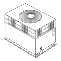
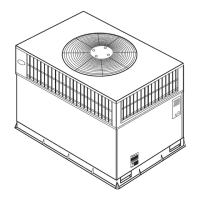
Fig. 6--Suggested Rigging
A05179
Accessory lifting kit is only to be used with Small Packaged
units which have a composite base pan with molded rigging
holds.
INSPECTION
Prior to initial use, and at monthly intervals, all rigging brackets
and straps should be visually inspected lbr any damage, evidence
of wear, structural delimnation, or cracks. Particular attention
should be paid to excessive wear at hoist hooking points and load
supporl areas. Brackets or straps showing any kind of wear in these
areas must not be used and should be discarded.
INSTALLATION
1. Position the lifting bracket assembly around the base of the
unit. Leave the top shipping skid on the unit to act as a
spreader bar. Be sure the strap does not twist.
2. Place each of the four (4) metal lifting brackets into the
rigging holds in the composite pan.
3. Tighten the ratchet strap unit tight. Lilting brackets should be
secure in the rigging holds.
4. Attach the clevis or book of sull'icient strength to hole in the
lifting bracket (See Fig. 6).
5. Attach safety straps directly to the field supplied rigging straps
or clevis clip. Do not attach the salbty straps to the lifting
brackets.
6. Use the top of the unit as a spreader bar to prevent the rigging
straps li"omdamaging the unit. B'the wood top is not available,
use a spreader bar of suflicient length to not damage the unit.
!
Lilting point should be directly over the center of gravity liar |
the unit.
J
Step 6--Connect Condensate Drain
NOTE: When installing condensate drain connection be sure to
comply with local codes and restrictions.
Models 5(tGS and 5(tGX dispose of condensate water through a
3/4 in. NPT fitting which exits through the base on the evaporator
coil access side. See Fig. 2 & 3 liar location.
Condensate water can be drained directly onto the roof in rooliop
installations (where permitted) or onto a gravel apron in ground-
level installations, lnstall a field-supplied condensate trap at end of
condensate connection to ensure proper drainage. Make sure that
the outlet of the trap is at least 1 in. lower than the drainpan
 Loading...