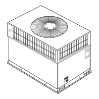
TabJe 2--PhysicaJ Data--Unit 50GX
030 036 042
2-1/2 3 3-1/2
291 299 321
Scroll
4.415.217.6
AccuRater®
.034
UNIT SIZE 048 060
NOMINAL CAPACITY (ton) 4 5
OPERATING WEIGHT (lb.) 326 399
COMPRESSOR
REFR,GERANT (R-22) [ 1Quantity (lb.) 8.3 8.1
REFRIGERANT METERING DEVICE
Orifice ID (in.) .030 .032 .034 .032
CONDENSER COIL
1...17 2...17 2...17 2...17 2...17
Rows...Fins/in.
12.7 9.1 9.1 12.3 16.4
Face Area (sq. ft.)
CONDENSER FAN
2350 2350 3300 3300 3300
Nominal Cfm
22 22 22 22 22
Diameter (in.) 1/8 (825) 1/8 (825) 1/4 (1100) 1/4 (1100) 1/4 (1100)
Motor Hp (Rpm)
EVAPORATOR COIL
3...18 3...15 3...15 4...15 4...15
Rows...Fins/in.
3.1 3.7 4.7 4.7 4.7
Face Area (sq. ft.)
EVAPORATOR BLOWER
1000 1200 1400 1600 1750
Nominal Airflow (Cfm) 10x10 1lx10 1lx10 1lx10 1lx10
Size (in.)
Motor Hp (RPM) 1/4 (1075) 1/2 (1075) 3/4 (1075) 3/4 (1075) 1.0 (1040)
RETURN-AIR FILTERS (in,)* 20x20 20x24 20x30 24x30 24x30
Throwaway
Required filter sizes shown are based on the larger of the ARI (Air Conditioning and Refrigeration Institute) rated cooling airflow or the heating airflow velocity of 300
ft./min, for throwaway type or 450 ft./rain, for high-capacity type. Air filter pressure drop for non-standard filters must not exceed 0.08 in. wg.
1" (25mm) MIN.
TRAP
OUTLET _
1
2" (50ram) MIN.
Fig. 7--Condensate Trap
Table 3--Minimum Airflow for Safe Electric Heater
Operation (Cfm)
SIZE 030 036 042 048 060
CFM 1000 1200 1400 1600 2000
C99013
12. Size all ductwork lk_r maximum required airflow (either
healing or cooling) lk_runit being installed. Avoid abrupt duct
size increases or decreases or perlormance may be afl_.:cted.
13. Adequately insulate and weatherproof all ductwork located
outdoors. Insulate ducts passing through unconditioned space,
and use vapor barrier in accordance with la_est issue of Sheet
Metal and Air Conditioning Contractors National Association
(SMACNA) and Air Conditioning Contractors of America
(ACCA) ndnimum installation standards lot heating and air
conditioning systems. Secure all ducts to building structure.
14. Flash, weatherproof, and vibration-isolate all openings in
building structure in accordance with local codes and good
building practices.
Step 8--Install Electrical Connection
The unit cabinet must have an uninterrupted, unbroken
electrical ground to minimize the possibility of personal
in,iury if an electrical fault should occur. This ground may
consist of an electrical wire connected to the unit ground lug
in the control compartment, or conduit approved l_r electrical
ground when installed in accordance with NEC (National
Electrical Code) ANSI/NFPA (latest edition) and local elec-
trical codes. In Canada, lollow Canadian Electrical Code
CSA (Canadian Standards Association) C22.1 and local
electrical codes. Failure to adhere to this warning could result
in personal injury or death.
 Loading...