15
System Mode (SYS)
In Run Status and Operating Modes, the current system mode is
displayed with expandable text. This is an overall state of the unit.
Three states are: Unit Operation Disabled, Unit Operation Enabled,
or Service Test Enabled.
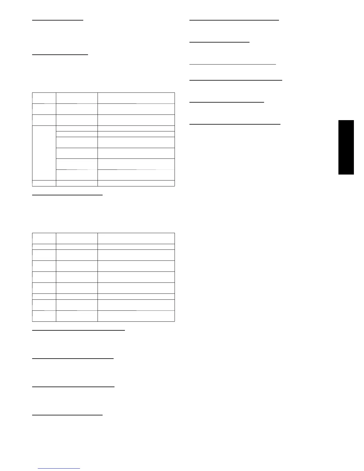
HVAC Mode (HVAC)
In Run Status and Operating Modes, the current allowed HVAC
mode is displayed with expandable text. This is the mode the unit
decides to run in based on its inputs. There are four main HVAC
modes; cooling has six different expanded texts. These modes are
shown below.
HVAC
Mode
Expanded Text Brief Description
Disabled HVAC Operation
Disabled
Unit is in test mode or System mode
is disabled
Fan Only Ventilation
( f a n --- o n l y )
Fanmayrunforventilation
Cooling
Cooling Mechanical cooling
Free Cooling Only economizer used for cooling
Unoccupied Free
Cooling
Only economizer use for cooling
(occupied cooling set point active)
Reheat1 All running circuits in sub---cooling
mode
Reheat2 All running circuits in Hot Gas Reheat
mode
Reheat1/Reheat2 Sub---cooling and Hot Gas Reheat
active
Heating Heating Heating mode
Indoor Fan Mode (F.MOD)
This displays the mode in which the fan is running. There are 8 fan
modes in total, the 1-Speed fans can only be in 1 of 2 modes (off or
High). Staged Air Volume (SAVt) units can utilize all 8 modes if
programmed for it. The table below shows the 8 modes and a brief
description for each.
Fan
Mode
Expanded Text Brief Description
0 OFF When the fan is off
1 High Whenfanisonin1---Speedunitsorat
high speed on SAV uni t s
2 Low Cool On SAV units with 2 cooling stages,
when only 1 cooling st age is request ed
3 Vent On SAV units, when in vent mode and
fan is on
4 IAQ Override On SAV units, i n any mo d e when IAQ
overri d e is acti v e
5 N/A Not available at this time
6 Dehum On SAV units , in cooling mode, and
specific conditions allow
7 Low Free Cool On SA V units, in cooli ng mode, and
specific conditions allow
HVAC Operation Disabled (HV.DN)
Allow disabling of HVAC mode. This is only available on a
network connection and shows if the unit has been forced into the
disabled status.
Cool Setpoint In Effect (EFF.C)
This shows the actual setpoint that is being used for control during
cooling mode. If a 0 is displayed, then space sensor control is not
being used and the unit is being controlled by a thermostat.
Heat Setpoint In Effect (EFF.H)
This shows the actual setpoint that is being used for control during
heating mode. If a 0 is displayed, then space sensor control is not
being used and the unit is being controlled by a thermostat.
Currently Occupied (OCC)
Displays the current state of assumed space occupancy based on
unit configuration and inputs.
Timed Override in Effect (T.OVR)
Displays if the state of occupancy is currently occupied due to an
override.
Linkage Active (LINK)
Displays if a linkage communication “Linkage” is established
between the unit and a linkage source.
Demand Limit in Effect (D.LMT)
Displays if a demand limit has been placed on the unit’s capacity.
Compressor OAT Lockout (C.LOC)
Displays if operation of one or more compressors is prevented due
to outdoor temperature limit lockout.
Heat OAT Lockout (H.LOC)
Displays if heating operation is prevented due to outdoor
temperature limit lockout.
Econo Cool OAT Lockout (E.LOC)
Displays if economizer operation for cooling is prevented due to
outdoor temperature limit lockout.
General Operation
48/50HC units can provide cooling, dehumidification, heating, and
ventilation operation. Each unit will operate under one of two
basic types of control: thermostat or space temperature sensor.
There are many inputs, configurations, safety factors, and
conditions that ultimately control the unit. Refer to the specific
operation sections for detail on a specific unit operation.
When thermostat control is enabled (ConfigurationUNIT
U.CTL = 1), the unit will operate based on discrete input
commands (G, Y1, Y2, W1, and W2) and there is a one minute
time delay between modes and when re--entering a mode. The G
command calls for ventilation, the Y1 and Y2 commands call for
cooling, and the W1 and W2 commands call for heating.
Thermostat Control Type (ConfigurationUNITT.CTL) affects
how cooling operates based on Y1 and Y2 commands and if
cooling/heating stage time guards are applied.
When space temperature sensor control is enabled (Configuration
UNITU.CTL = 2), the unit will try to maintain the Space
Temperature (TemperaturesAIR.TSPT) between the effective
cool and heat setpoints (Run StatusMODEEFF.C and
EFF.H). However, to minimize unnecessary cool to heat and heat
to cool changes, there is a 10 minute delay after the last stage turns
off before the control will switch modes and a 1 minute delay when
re--entering the last mode. Linkage operation overrides the mode
changeover delay to 15 seconds. The cooling and heating Mode
Select Timeguard (Operating ModesCOOLMS.TG and
Operating ModesHEATMS.TG) show the remaining time
before allowing the respective mode to be entered.
Temperature Setpoint Determination
Setpoints are used to control the unit while under space
temperature sensor control. The Cool Setpoint in Effect (EFF.C)
and the Heat Setpoint in Effect (EFF.H) are the points in which the
unit is controlling to at a specific time. These points are read only
points and change according to occupancy, the offset slider status,
and network writes (Linkage or LON).
If the building is in occupied mode, the Occupied Cool Setpoint
(SetpointsOCSP) and the Occupied Heat Setpoint (Setpoints
OHSP) are active. When the building is in unoccupied mode,
the Unoccupied Cool Setpoint (SetpointsUCSP)andthe
Unoccupied Heat Setpoint (SetpointsUHSP) are active. The
heating and cooling set points are also separated by a Heat--Cool
Set Point Gap (SetpointsGAP) that is user configurable from 2
to 10 degrees F. This parameter will not allow the setpoints to be
set too close together, it will change the last setpoint adjusted if it is
set within the GAP.
ComfortLINK v1.X
 Loading...


