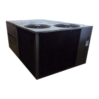
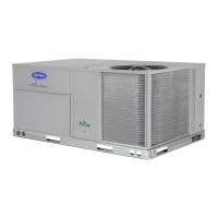
Manufacturer reserves the right to discontinue, or change at any time, specifications or designs without notice and without incurring obligations.
PC 111 Catalog No. 534-80090 Printed in U.S.A. Form 48/50HG-2T Pg 1 202 10-01 Replaces: 48/50HG-1T
Book 1144
Tab 1a1b6a6b
Controls Operation and Troubleshooting
CONTENTS
SAFETY CONSIDERATIONS
. . . . . . . . . . . . . . . . . . . . . . 1
GENERAL
. . . . . . . . . . . . . . . . . . . . . . . . . . . . . . . . . . . . . . . . 1
MAJOR SYSTEM COMPONENTS
. . . . . . . . . . . . . . .1-11
General
. . . . . . . . . . . . . . . . . . . . . . . . . . . . . . . . . . . . . . . . . . 1
Main Base Board (MBB)
. . . . . . . . . . . . . . . . . . . . . . . . . . 1
Economizer Control Board (ECB)
. . . . . . . . . . . . . . . . 2
Scrolling Marquee Display
. . . . . . . . . . . . . . . . . . . . . . . 2
Board Addresses
. . . . . . . . . . . . . . . . . . . . . . . . . . . . . . . . . 2
Control Module Communication
. . . . . . . . . . . . . . . . . . 2
• RED LED
• GREEN LED
• YELLOW LED
Carrier Comfort Network Interface
. . . . . . . . . . . . . . . . 2
Field-Installed Accessories
. . . . . . . . . . . . . . . . . . . . . . 2
• SPACE TEMPERATURE SENSOR (T55)
• SPACE TEMPERATURE SENSOR (T56)
• SPACE TEMPERATURE SENSOR (T58)
• SPACE TEMPERATURE SENSOR CALIBRATION
• ECONOMIZER
• POWER EXHAUST
• INDOOR AIR QUALITY
• SMOKE DETECTOR
• FILTER STATUS
• FAN STATUS
• ENTHALPY SENSORS
CONTROLS AND FUNCTIONS
. . . . . . . . . . . . . . . . 11-25
Marquee Display Usage
. . . . . . . . . . . . . . . . . . . . . . . . . 11
Clearing Unit Alarms
. . . . . . . . . . . . . . . . . . . . . . . . . . . . 11
Service Test
. . . . . . . . . . . . . . . . . . . . . . . . . . . . . . . . . . . . . 12
OPERATION
. . . . . . . . . . . . . . . . . . . . . . . . . . . . . . . . . . 26-31
Unit Control Type (U.CTL)
. . . . . . . . . . . . . . . . . . . . . . . 26
Occupancy Determination
. . . . . . . . . . . . . . . . . . . . . . . 26
Indoor Fan
. . . . . . . . . . . . . . . . . . . . . . . . . . . . . . . . . . . . . . 26
Outdoor Fans
. . . . . . . . . . . . . . . . . . . . . . . . . . . . . . . . . . . 27
Economizer
. . . . . . . . . . . . . . . . . . . . . . . . . . . . . . . . . . . . . 27
Indoor Air Quality (IAQ)
. . . . . . . . . . . . . . . . . . . . . . . . . 27
Power Exhaust
. . . . . . . . . . . . . . . . . . . . . . . . . . . . . . . . . . 28
Compressor Staging
. . . . . . . . . . . . . . . . . . . . . . . . . . . . 28
Heating (48HG Units)
. . . . . . . . . . . . . . . . . . . . . . . . . . . . 28
• THERMOSTAT CONTROL
• SPACE SENSOR CONTROL
Heating (50HG Units)
. . . . . . . . . . . . . . . . . . . . . . . . . . . . 29
• THERMOSTAT CONTROL
• SPACE SENSOR CONTROL
Cooling
. . . . . . . . . . . . . . . . . . . . . . . . . . . . . . . . . . . . . . . . . 30
• THERMOSTAT CONTROL
• SPACE SENSOR CONTROL
Space Temperature Sensor Calibration
and Trim
. . . . . . . . . . . . . . . . . . . . . . . . . . . . . . . . . . . . . . 31
Alarm Handling
. . . . . . . . . . . . . . . . . . . . . . . . . . . . . . . . . 31
TROUBLESHOOTING
. . . . . . . . . . . . . . . . . . . . . . . . . 31-39
Complete Unit Stoppage
. . . . . . . . . . . . . . . . . . . . . . . . 31
Single Circuit Stoppage
. . . . . . . . . . . . . . . . . . . . . . . . . 31
Service Analysis
. . . . . . . . . . . . . . . . . . . . . . . . . . . . . . . . 31
Restart Procedure
. . . . . . . . . . . . . . . . . . . . . . . . . . . . . . . 31
Alarms and Alerts
. . . . . . . . . . . . . . . . . . . . . . . . . . . . . . . 32
Page
• DIAGNOSTIC ALARM CODES AND
POSSIBLE CAUSES
Thermistor Troubleshooting
. . . . . . . . . . . . . . . . . . . . . 39
• THERMISTOR/TEMPERATURE SENSOR CHECK
Transducer Troubleshooting
. . . . . . . . . . . . . . . . . . . . 39
START-UP
. . . . . . . . . . . . . . . . . . . . . . . . . . . . . . . . . . . . 39-43
APPENDIX A — CCN TABLES
. . . . . . . . . . . . . . . . 44-52
CONTROL SET-UP CHECKLIST
. . . . . . . . . .CL-1, CL-2
SAFETY CONSIDERATIONS
Installation and servicing of air-conditioning equipment can
be hazardous due to system pressure and electrical compo-
nents. Only trained and qualified service personnel should
install, repair, or service air-conditioning equipment. Untrained
personnel can perform the basic maintenance functions of
replacing filters. All other operations should be performed by
trained service personnel. When working on air-conditioning
equipment, observe precautions in the literature, tags and labels
attached to the unit, and other safety precautions that may
apply. Follow all safety codes. Wear safety glasses and work
gloves. Use quenching cloth for unbrazing operations. Have
fire extinguishers available for all brazing operations.
GENERAL
This publication contains Start-Up, Controls, Operation,
and Troubleshooting information for the 48/50HG rooftop
units. See Table 1. These units are equipped with ComfortLink
controls.
Table 1 — Unit Sizes (48/50HG)
MAJOR SYSTEM COMPONENTS
General —
The 48/50HG single package rooftop units with
electric cooling and with gas heating (48HG units) or electric
cooling and electric heating (50HG Units) contain the
ComfortLink electronic control system that monitors all opera-
tions of the rooftop. The control system is composed of several
components as listed in sections below. See Fig. 1-3 for the
control and power schematics. Figure 4 shows the layout of the
control box, unit, and thermistor and transducer locations.
Main Base Board (MBB) —
See Fig. 5. The MBB is
the center of the ComfortLink control system. It contains the
major portion of the operating software and controls the opera-
tion of the unit. The MBB continuously monitors input/output
channel information received from its inputs and from the
Economizer Control Board (ECB). The MBB receives inputs
UNIT MODEL NOMINAL TONS
48/50HG014
12
1
/
2
48/50HG016
15
48/50HG020
18
48/50HG024
20
48/50HG028
25
48/50HG014-028
Single Package Large Rooftop Units
with
Comfort
Link™ Controls


 Loading...