18
OPTIONAL ECONOMI$ER IV AND ECONOMI$ER2 —
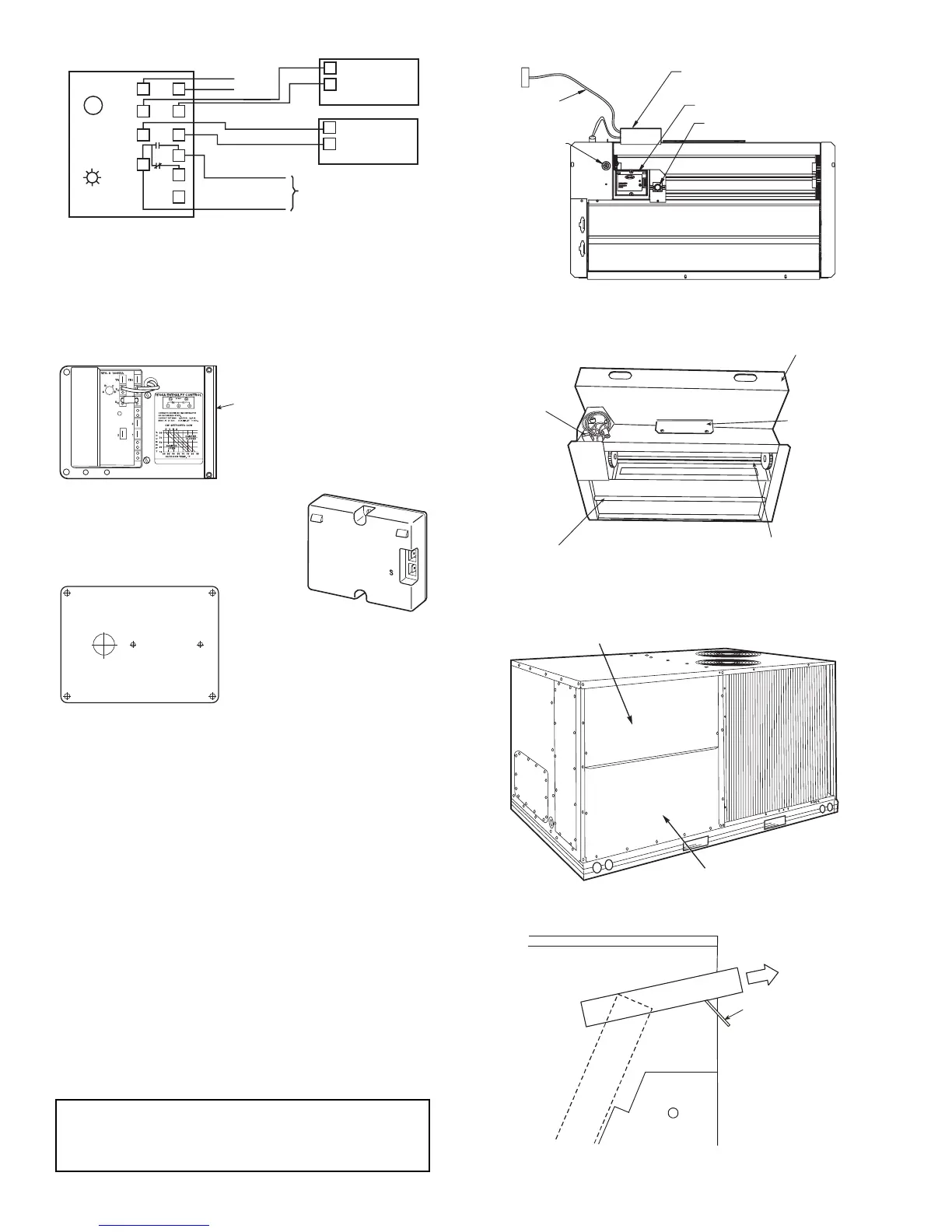
See Fig. 24 for EconoMi$er IV component locations. See
Fig. 25 for EconoMi$er2 component locations.
NOTE: These instructions are for installing the optional
EconoMi$er IV and EconoMi$er2 only. Refer to the accessory
EconoMi$er IV or EconoMi$er2 installation instructions when
field installing an EconoMi$er IV or EconoMi$er2 accessory.
1. To remove the existing unit filter access panel, raise the
panel and swing the bottom outward. The panel is now
disengaged from the track and can be removed. See
Fig. 26.
2. The box with the economizer hood components is
shipped in the compartment behind the economizer. The
EconoMi$er IV controller is mounted on top of the
EconoMi$er IV in the position shown in Fig. 24. The op-
tional EconoMi$er2 with 4 to 20 mA actuator signal con-
trol does not include the EconoMi$er IV controller. To re-
move the component box from its shipping position, re-
move the screw holding the hood box bracket to the top
of the economizer. Slide the hood box out of the unit. See
Fig. 27.
IMPORTANT: If the power exhaust accessory is to be
installed on the unit, the hood shipped with the unit will not
be used and must be discarded. Save the aluminum filter
for use in the power exhaust hood assembly.
BRACKET
+
C
7400A1004
Fig. 23 — Differential Enthalpy Control,
Sensor and Mounting Plate (33AMKITENT006)
HH57AC077
ENTHALPY
CONTROL AND
OUTDOOR AIR
ENTHALPY SENSOR
HH57AC078 ENTHALPY SENSOR
(USED WITH ENTHALPY
CONTROL FOR
DIFFERENTIAL ENTHALPY
OPERATION)
MOUNTING PLATE
LED
A
B
C
D
TR TR1
SO
SR
2
3
1
+
+
BRN
RED
GRAY/ORN
GRAY/RED
WIRE HARNESS
IN UNIT
BLK
RED
S
+
(RETURN AIR
ENTHALPY
SENSOR)
S
+
(OUTDOOR
AIR
ENTHALPY
SENSOR)
ENTHALPY CONTROLLER
NOTES:
1. Remove factory-installed jumper across SR and + before connecting
wires from return air sensor.
2. Switches shown in high outdoor air enthalpy state. Terminals 2 and 3
close on low outdoor air enthalpy relative to indoor air enthalpy.
3. Remove sensor mounted on back of control and locate in outside
airstream.
Fig. 22 — Outdoor and Return Air Sensor Wiring
Connections for Differential Enthalpy Control
Fig. 24 — EconoMi$er IV Component Locations
ECONOMI$ER IV
CONTROLLER
OUTSIDE AIR
TEMPERATURE SENSOR
LOW AMBIENT
SENSOR
ACTUATOR
WIRING
HARNESS
Fig. 25 — EconoMi$er2 Component Locations
FILTER ACCESS PANEL
INDOOR COIL ACCESS PANEL
Fig. 26 — Typical Access Panel Locations
H
o
o
d
B
o
x
HOOD BOX
BRACKET
Fig. 27 — Hood Box Removal
ECONOMI$ER2
PLUG
BAROMETRIC
RELIEF
DAMPER
OUTDOOR
AIR HOOD
HOOD
SHIPPING
BRACKET
GEAR DRIVEN
DAMPER
 Loading...

