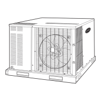
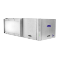
Dimensions (cont)
SIZES 042-060 WITH OPTIONAL BASE RAIL
UNIT
ELECTRICAL
CHARACTERISTICS
UNIT WT CORNER WT (Lb/Kg)
Lb Kg A B C D
50HS042,048 208/230-1-60, 208/230-3-60, 460-3-60 379 172 94/43 86/39 118/54 81/37
50HS060 208/230-1-60, 208/230-3-60, 460-3-60 393 179 97/44 90/41 121/55 85/39
UNIT
CENTER OF GRAVITY (in./mm)
XYZ
50HS042,048 19.6/498 20.6/524 17.3/440
50HS060 19.6/497 20.6/524 17.3/440
REQ’D CLEARANCES FOR SERVICING — in. (mm)
Indoor Coil Access Side ...........................30(762)
Control Box Access Side (Except for NEC requirements) ..........30(762)
Unit Top ...................................36(914)
Side Opposite Ducts ............................30(762)
REQ’D CLEARANCES TO COMBUSTIBLE MAT’L — in. (mm)
Unit Top .......................................0
Duct Side of Unit ..................................0
Side Opposite Ducts ................................0
Bottom of Unit ...................................0
Vertical Discharge, First 12 in. (305) of Supply Duct .............1(25)
NEC REQ’D CLEARANCES — in. (mm)
Between Units, Control Box Side .............42(1067)
Unit and Ungrounded Surfaces, Control Box Side ......36(914)
Unit and Block or Concrete Walls and Other
Grounded Surfaces, Control Box Side ..........42(1067)
LEGEND
CG — Center of Gravity
MAT’L — Material
NEC — National Electrical Code
REQ’D — Required
NOTES:
1. Clearances must be maintained to prevent recirculation of air from
outdoor-fan discharge.
2. Dimensions in ( ) are in mm.
8

 Loading...