EasyManua.ls Logo

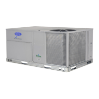
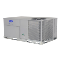
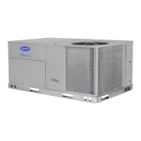
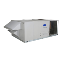
Carrier 50TC-D12 User Manual

Carrier 50TC-D12
40 pages
To Next Page IconTo Next Page
Page #1 background imageLoading...
Page #1 background image
50TC
Single Package Rooftop, 50Hz
Cooling Only
Sizes 07, 08, 09, and 12
with Puronr (R---410A) Refrigerant
Installation Instructions
NOTE: This manual discusses only the mechanical
installation of this unit. Star--up procedures, operating
sequences and service instructions are included in a
separate Service/Maintenance manual which is not
included with this unit. Other manuals may be required
for specific factory--installed options.
Read through the entire installation instruction manual
before starting the installation, to familiarize yourself with
all steps and to identify additional reference materials
required.
Contact your local Carrier representative for additional
service reference materials.
TABLE OF CONTENTS
SAFETY CONSIDERATIONS 1....................
INSTALLATION 6...............................
Step 1 -- Plan for Unit Location 6..................
Step 2 -- Plan for Sequence of Unit Installation 7......
Step 3 -- Inspect Unit 7...........................
Step 4 -- Provide Unit Support 7...................
Step 5 -- Field Fabricate Ductwork 10...............
Step 6 -- Rig and Place Unit 11....................
Step 7 -- Convert to Horizontal & Connect Ductwork 11
Step 8 -- Install Outside Air Hood 11...............
Step 9 -- Install External Condensate Trap and Line 13.
Step 10 -- Make Electrical Connections 13...........
Step 11 -- Adjust Factory--Installed Options 35........
Step 12 -- Install Accessories 35...................
SAFETY CONSIDERATIONS
Improper installation, adjustment, alteration, service,
maintenance, or use can cause explosion, fire, electrical
shock or other conditions which may cause personal
injury or property damage. Consult a qualified installer,
service agency, or your distributor or branch for
information or assistance. The qualified installer or
agency must use factory--authorized kits or accessories
when modifying this product. Refer to the individual
instructions packaged with the kits or accessories when
installing.
Follow all safety codes. Wear safety glasses and work
gloves. Use quenching cloths for brazing operations and
have a fire extinguisher available. Read these instructions
thoroughly and follow all warnings or cautions attached to
the unit. Consult local building codes for special
requirements. In absence of local codes, it is
recommended that the USA standard ANSI/NFPA 70,
National Electrical Code (NEC), be followed.
It is important to recognize safety information. This is the
safety--alert symbol
. When you see this symbol on the
unit and in instructions or manuals, be alert to the
potential for personal injury.
Understand the signal words DANGER, WARNING,
CAUTION, and NOTE. These words are used with the
safety--alert symbol. DANGER identifies the most serious
hazards which will result in severe personal injury or
death. WARNING signifies hazards which could result in
personal injury or death. CAUTION is used to identify
unsafe practices, which may result in minor personal
injury or product and property damage. NOTE is used to
highlight suggestions which will result in enhanced
installation, reliability, or operation.

Table of Contents

Question and Answer IconNeed help?

Do you have a question about the Carrier 50TC-D12 and is the answer not in the manual?

Carrier 50TC-D12 Specifications

General IconGeneral
BrandCarrier
Model50TC-D12
CategoryAir Conditioner
LanguageEnglish

Summary

Safety Considerations

Hazard Signal Words

Understanding DANGER, WARNING, CAUTION, and NOTE signal words.

Safety Warnings

Electrical and Operational Hazards

Warnings for electrical shock, unit operation, personal injury, and environmental risks.

Cut Hazard and Safety Precautions

Caution regarding sharp metal edges and general safety attire.

Unit Dimensional Drawings

07 Size Unit Dimensions and Connections

Diagrams showing dimensions and connection points for 07 size units.

Unit Dimensional Drawings (cont.)

07 Size Unit Dimensions and Weight Data

Continued dimensional drawings and weight data for 07 size units.

Unit Dimensional Drawings

08, 09, 12 Size Unit Dimensions and Connections

Diagrams showing dimensions and connection points for 08, 09, 12 size units.

Installation Steps

Jobsite Survey and Location Planning

Pre-installation checks including codes, location, and obstruction assessment.

Installation Steps (cont.)

Sequence and Unit Support Planning

Recommended installation sequences and unit support methods (curb, slab).

Unit Inspection and Preparation

Procedures for unit inspection and preparing for support installation.

Roof Curb Installation Details

07 Size Unit Roof Curb Details

Diagram and notes for installing roof curb accessory on 07 size units.

Roof Curb Installation Details

08-12 Size Unit Roof Curb Details

Diagram and notes for installing roof curb accessory on 08-12 size units.

Field Ductwork and Rigging

Field Fabricate Ductwork

Instructions for fabricating ductwork and rigging details.

Unit Placement and Ductwork Conversion

Rig and Place Unit

Procedures for safely rigging, lifting, and positioning the unit on its support.

Convert to Horizontal Ductwork

Instructions for converting the unit to a horizontal duct configuration.

Install Outside Air Hood

Procedures for installing the outside air hood, including economizer options.

Economizer Hood and Damper Setup

Economizer Hood and Two-Position Hood

Detailed steps for assembling and installing economizer hoods and dampers.

Condensate and Electrical Connections

Install External Condensate Trap and Line

Guidance on installing external condensate traps and lines for proper drainage.

Make Electrical Connections

Instructions for making safe and compliant electrical connections to the unit.

Electrical Connections (cont.)

Disconnect Switch and Power Wiring

Information on disconnect switch installation and power wiring configurations.

Control Wiring

Field Control Wiring and Thermostat Setup

Guidelines for field wiring of control devices and thermostats.

Electric Heater Installation

Electric Heaters Overview

Information on accessory electric heater modules and their installation.

Electric Heater Wiring

Accessory Electric Heater Control Wiring

Specific wiring instructions for accessory electric heater control connections.

PremierLink Controller

PremierLink Controller Overview and Mounting

Description of the PremierLink controller and its mounting location.

PremierLink Wiring Schematic

Wiring schematic for the PremierLink controller.

PremierLink Controller Features

PremierLink Sensor Usage and Modes

Details on sensor usage, modes, and tables for sensor configurations.

PremierLink Controller Features (cont.)

PremierLink Thermostat and Economizer Controls

Connecting thermostats, economizer controls, and enthalpy sensors.

PremierLink Air Quality and Discrete Inputs

Wiring for CO2 sensors, filter status, and remote occupancy inputs.

PremierLink Controller Features (cont.)

PremierLink Communication and Troubleshooting

CCN bus wiring, protocols, and troubleshooting with LEDs.

RTU-MP Control System

RTU-MP Control Board and Wiring Diagram

Overview of the RTU-MP control board and its system wiring diagram.

RTU-MP Controller Inputs/Outputs and Sensors

Table of RTU-MP inputs/outputs and sensor connection details.

RTU-MP Control System Features

RTU-MP Discrete Inputs and Communication Wiring

Connecting discrete inputs like CO2 and filter status, and communication wiring.

RTU-MP Control System Features (cont.)

RTU-MP Troubleshooting and Local Access

Information on RTU-MP LEDs, BACview handheld, and troubleshooting.

Factory-Installed Options & Accessories

Adjust Factory-Installed Options

Procedures for adjusting factory-installed options like EconoMi$er IV occupancy.

Install Available Accessories

List of available accessories and reference to their installation instructions.

Pre-Start and Start-Up Procedures

Reference to the Service Manual for detailed pre-start and start-up instructions.

Unit Wire/MOCP Sizing Data

Electric Heater Sizing Data

Tables detailing wire and MOCP sizing for electric heaters.
Related product manuals