(2.) Inducer motor operates for 20 sec at low speed,
operates for 20 sec at high speed, then turns off.
(3.) Hot surface ignitor is energized for 15 sec, then
de-energized.
(4.) Main blower motor operates for 20 sec at low speed,
operates at high speed for 20 sec, then turns off.
(5.) After component operation test is completed, 1 or
more fault codes (11, 22, 41, or 42) will flash. See
service label on back of main furnace door or Fig 21
for explanation of codes.
g. Release blower access panel door switch and turn setup
switch SW-6 to OFF position.
h. Replace blower access panel.
i. Operate furnace through 1 heat cycle to check for proper
operation and check LED status.
j. If furnace is operating properly and LEDs indicate proper
operation, replace main furnace door.
Step 9—Check Heat Tape Operation (If Applicable)
In applications where the ambient temperature around the furnace
is 32°F or lower, freeze protection measures are required. If this
application is where heat tape has been applied, check to ensure it
will operate when low temperatures are present.
NOTE: Heat tape, when used, should be wrapped around the
condensate drain trap and drain line. There is no need to use heat
tape within the furnace casing. Most heat tapes are temperature
activated, and it is not practical to verify the actual heating of the
tape. Check the following:
1. Check for signs of physical damage to heat tape such as nicks,
cuts, abrasions, gnawing by animals, etc.
2. Check for discolored heat tape insulation. If any damage or
discolored insulation is evident, replace heat tape.
3. Check that heat tape power supply circuit is on.
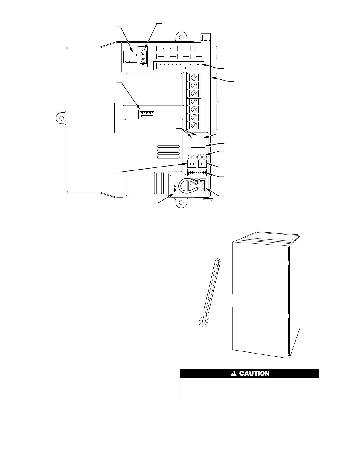
Fig. 15—Variable Control Center
A93062
P3
P1
W2
COM
24V
W/W2 Y/Y2
R G
HUM
P4
HOT SURFACE
IGNITOR CONNECTOR
EAC-ELECTRONIC AIR
CLEANER TERMINALS
(115-VAC 1 AMP MAX)
115-VOLT
CONNECTORS
24-VOLT THERMOSTAT
TERMINALS
PRESSURE SWITCH
CONNECTOR
HUM-HUMIDIFIER
TERMINAL
(24-VAC 0.5 AMP MAX)
TRANSFORMER
24-VOLT CONNECTORS
3-AMP FUSE
STATUS AND DIAGNOSTIC
LED LIGHTS
AIR CONDITIONING
(A/C) SETUP SWITCH
SETUP SWITCHES
(SW) AND BLOWER
OFF DELAY SETUP
SWITCHES
MODEL PLUG
COMMUNICATION
CONNECTOR
CONTINUOUS
FAN (CF) SETUP
SWITCHES
MAIN BLOWER
CONTROL WIRE
CONNECTOR
DEHUMIDIFIER (DH)
CONNECTOR
If this furnace is installed in an unconditioned space where
the ambient temperatures may be 32°F or lower, freeze
protection measures must be taken.
A93058
32°F MINIMUM INSTALLED
AMBIENT OR FREEZE
PROTECTION REQUIRED
12

 Loading...


