14. Reinstall burner box pressure tube to gas valve regulator
fitting.
15. Reinstall gas supply pipe to gas valve using backup wrench on
gas valve to prevent rotation and improper orientation.
NOTE: Use propane gas resistant pipe dope to prevent gas leaks.
DO NOT use Teflon tape.
Gas valve knob MUST be facing forward or tilted upward.
Failure to follow this warning could result in property
damage, personal injury, or death.
16. Replace burner box cover.
17. Replace furnace door.
18. Turn on gas and electrical supplies to furnace.
Step 4—Clean Heat Exchangers
The following items should be performed by a qualified service
technician.
PRIMARY HEAT EXCHANGERS
If the heat exchangers get an accumulation of light dirt or dust on
the inside, they may be cleaned by the following procedure:
NOTE: If the heat exchangers get a heavy accumulation of soot
and carbon, both the primary and secondary heat exchangers
should be replaced rather than trying to clean them thoroughly due
to their intricate design. A build-up of soot and carbon indicates
that a problem exists which needs to be corrected, such as
improper adjustment of manifold pressure, insufficient or poor
quality combustion air, improper vent termination, incorrect size
or damaged manifold orifice(s), improper gas, or a restricted heat
exchanger (primary or secondary). Action must be taken to correct
the problem.
1. Turn off gas and electrical supplies to furnace.
2. Remove furnace door.
3. Disconnect wires or connectors to overtemperature switch, gas
valve, ignitor, and flame sensor.
4. Disconnect combustion-air intake pipe from intake housing.
5. Remove the pressure switch tube from intake housing.
6. Remove screws attaching intake housing to burner box, and
rotate intake housing away from burner box for removal.
7. Using backup wrench, disconnect gas supply pipe from gas
valve.
8. Disconnect pressure tubing from gas valve.
9. Remove 2 screws attaching top filler panel and rotate upwards
to gain access to screws attaching burner box to cell panel.
10. Remove screws attaching burner box to cell panel. (See Fig.
5.)
NOTE: Burner box cover, manifold, gas valve, and burner
assembly should be removed as 1 assembly.
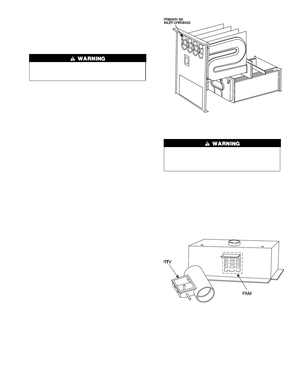
11. Clean heat exchanger openings with a vacuum and a soft
brush. (See Fig. 6.)
NOTE: After cleaning, inspect the heat exchangers to ensure they
are free of all foreign objects that may restrict flow of combustion
products.
12. Reverse steps 4 through 10 for reassembly.
The ground wire from the gas valve MUST be attached to the
burner box attachment screw. Failure to attach this ground
wire to an adequate casing ground will cause the furnace
control to lock out.
NOTE: Be sure burner box gasket is installed between burner box
and cell panel. If gasket is damaged, replace it.
NOTE: Inspect combustion-air intake housing. If foamed gasket
was removed, check for any damage. If gasket is damaged in any
way, it must be repaired. To repair, remove damaged gasket
section, apply sealant releasing agent (PAM cooking spray or
equivalent, must not contain corn or canola oil, aromatic or
halogenated hydrocarbons) to burner box and apply a small bead
of G.E. RTV 162 or Dow-Corning RTV 738 sealant to edge of
combustion-air intake housing. (See Fig. 7.)
13. Refer to furnace wiring diagram and connect wires to rollout
(overtemperature) switch, gas valve, ignitor, and flame sensor.
14. Reconnect pressure switch tubes to gas valve and intake
housing. See diagram on blower access panel for proper
location of tubes. Be sure tubes are not kinked. (See Fig. 8 or
9.)
15. Turn on gas and electrical supplies to furnace.
Fig. 6—Cleaning Inlet Openings of Primary Heat
Exchangers
A93080
Fig. 7—Combustion-Air Intake Housing Gasket Re-
pair
A93087
5

 Loading...


