-- 4 2 --
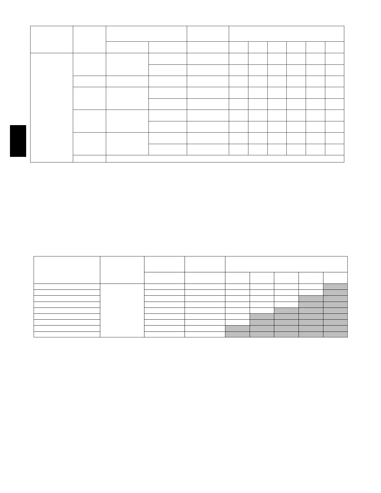
Table 11—Maximum Allowable Pipe Length -- Ft (M) (Continued)
ALTITUDE
FT (M)
UNIT SIZE
(BTUH)
DIRECT VENT (2-PIPE) ONLY
NON-DIRECT
VENT (1-PIPE)
ONLY
NUMBER OF 90° ELBOWS
TERMINATION
TYPE
PIPE DIA
IN. (mm)*
PIPE DIA
IN. (mm)*
1 2 3 4 5 6
9001 to 10,000‡
(2743 to 3048)
40,000
2Pipeor2-in 1-1/2 (38) 1-1/2 (38)
42
(12.8)
37
(11.3)
32
(9.8)
27
(8.2)
25
(7.6)
20
(6.1)
Concentric 2 (51) 2 (51)
57
(17.4)
55
(16.8)
53
(16.2)
51
(15.5)
49
(14.9)
47
(14.3)
60,000
2Pipeor2-in
Concentric
2 (51) 2 (51)
45
(13.7)
40
(12.2)
38
(11.6)
33
(10.1)
31
(9.4)
29
(8.8)
80,000
2Pipeor2-in
Concentric
2 (51) 2 (51)
30
(9.1)
25
(7.6)
14
(4.3)
9
(2.7)
7
(2.1)
NA
2-1/2 (64) 2-1/2 (64)
57
(17.4)
55
(16.8)
53
(16.2)
51
(15.5)
49
(14.9)
47
(14.3)
100,000
2Pipeor3-in
Concentric
2-1/2 (64) 2-1/2 (64)
21
(6.4)
13
(4.0)
5
(1.5)
NA NA NA
3 (76) 3 (76)
54
(16.5)
49
(14.9)
44
(13.4)
39
(11.9)
34
(10.4)
29
(8.8)
120,000
2Pipeor3-in.
Concentric
NA 3 (76)†
39
(11.9)
37
(11.3)
35
(10.7)
33
(10.1)
31
(9.4)
29
(8.8)
4 (102)† no
disk
4 (102)† no disk
10
(3.0)
5
(1.5)
NA NA NA NA
140,000 NA
* Disk usage -Unless otherwise specified, use perforated disk assembly (factory-supplied in loose parts bag).
# If one disk is stated, separate 2 halves of perforated disk assembly and use shouldered disk half. When using shouldered disk half, install screen sidetowardinletbox.
† Wide radius elbow.
‡ Vent sizing for Canadian installations over 4500 ft (1370 M) above sea level are subject to acceptance by the local authorities having jurisdiction. NA-Not Allowed;
pressure switch will not make.
NOTES:
1. Do not use pipe size greater than those specified in table or incomplete combustion, flame disturbance, or flame sense lockout may occur.
2. Size both the combustion-air and vent pipe independently, then use the larger diameter for both pipes.
3. Assume two 45° elbows equal one 90° elbow . Wide radius elbows are desirableandmayberequiredinsomecases.
4. Elbows and pipe sections within the furnace casing and at the vent termination should not be included in vent length or elbow count.
5. The minimum pipe length is 5 ft (1.5 M) for all applications.
6. Use 3-in. (76 mm) diameter vent termination kit for installations requiring 4-in (102 mm) diameter pipe.
Table 12 – Vent Length for Outlet Restrictor Usage (60,000 btu model only) -- Ft (M)}
ALTITUDE --- FT (M) UNIT SIZE
DIRECT VENT
(2---PIPE)
N O N --- D I R E C T
VENT
(1---PIPE ONLY)
NO. OF 90_ ELBOWS
PIPE DIA.
(IN / mm)
PIPE DIA.
(IN / mm)
1 2 3 4 5
0 --- 2000 (0 --- 610)
60,000
2 --- i n . ( 5 1 ) 2 --- i n . ( 5 1) 28 (8.5) 20 (6) 15 (4.2) 10 (3)
2001 --- 3000 (610 --- 914) 2 --- i n . ( 5 1 ) 2 --- i n . ( 5 1) 24 (7.3) 17 (5.1) 12 (3.6) 7 (2.1)
3001 --- 4000 (914 --- 1219) 2 --- i n . ( 5 1 ) 2 --- i n. ( 5 1) 21 (6.4) 13 (3.9) 8 (2.4)
4001 --- 5000 (1219 --- 1524) 2 --- i n . ( 5 1 ) 2 --- i n. ( 5 1) 17 (5.1) 10 (3) 5 (1.5)
5001 --- 6000 (1524 --- 1829) 2 --- i n . ( 5 1 ) 2 --- i n. ( 5 1) 14 (4.2) 6 (1.8)
6001 --- 7000 (1829 --- 2134) 2 --- i n . ( 5 1 ) 2 --- i n. ( 5 1) 10 (3)
7001 --- 8000 (2134 --- 2438) 2 --- i n . ( 5 1 ) 2 --- i n. ( 5 1) 6 (1.8)
8001 --- 9000 (2438 --- 2743) 2 --- i n . ( 5 1 ) 2 --- i n. ( 5 1)
9001 --- 10000 (2743 --- 3048) 2 --- i n . ( 5 1 ) 2 --- i n. ( 5 1)
}Discard outlet restrictor if vent lengths or elbows exceed the above table Discard restrictor if using 11/2---in. (38mm) diameter pipe. See Fig. 37 and38for
proper installation.
58MCB