Step 9—Removal of Existing Furnaces from
Common Vent Systems
When an existing Category I furnace is removed or replaced, the
original venting system may no longer be sized to properly vent
the remaining attached appliances. An improperly sized Category
I venting system could cause the formation of condensate in the
furnace and vent, leakage of condensate and combustion products,
spillage of combustion products into the living space, etc.
Step 10—Combustion Air and Vent Pipe Systems
GENERAL
Vent system or vent connectors may need to be resized. For any
other appliances when resizing vent systems or vent connectors,
system or connector must be sized to approach minimum size as
determined using appropriate table found in the NFGC or NSC-
NGPIC.
The 58MTB can be vented as either a direct vent (all sizes) or as
a non-direct vent (except for 140 size) application. A direct vent
system shall be installed in accordance with the direct vent
(2-pipe) procedures in the following Combustion Air and Vent
Pipe Systems section. For non-direct vent (1-pipe) applications,
refer to the non-direct vent (1-pipe) procedures in the same section.
Multistory and common venting are prohibited.
DIRECT VENT/2-PIPE SYSTEM
In a direct-vent (2-pipe) system, all air for combustion is taken
directly from outdoor atmosphere, and all flue products are
discharged to outdoor atmosphere. A factory accessory vent
termination kit MUST be used in a direct vent (2-pipe) system.
NON-DIRECT VENT/1-PIPE SYSTEM
In a non-direct vent (1-pipe) system, all air for combustion is taken
from the area adjacent to furnace, and all flue products are
discharged to outdoor atmosphere. A factory-supplied perforated
disk assembly (in loose parts bag) MUST be used in combustion-
air pipe elbow.
CARBON MONOXIDE POISONING HAZARD
Failure to follow the steps outlined below for each appliance
connected to the venting system being placed into operation
could result in carbon monoxide poisoning or death.
The following steps shall be followed for each appliance
connected to the venting system being placed into operation,
while all other appliances connected to the venting system are
not in operation:
1. Seal any unused openings in venting system.
2. Inspect the venting system for proper size and horizontal
pitch, as required in the National Fuel Gas Code, ANSI
Z223.1-2002/NFPA 54-2002 or the CSA B149.1, Natural
Gas and Propane Installation Code and these instructions.
Determine that there is no blockage or restriction, leakage,
corrosion and other deficiencies, which could cause an
unsafe condition.
3. As far as practical, close all building doors and windows
and all doors between the space in which the appliance(s)
connected to the venting system are located and other
spaces of the building.
4. Close fireplace dampers.
5. Turn on clothes dryers and any appliance not connected to
the venting system. Turn on any exhaust fans, such as
range hoods and bathroom exhausts, so they are operating
at maximum speed. Do not operate a summer exhaust fan.
6. Follow the lighting instructions. Place the appliance being
inspected into operation. Adjust the thermostat so appli-
ance is operating continuously.
7. Test for spillage from draft hood equipped appliances at the
draft hood relief opening after 5 minutes of main burner
operation. Use the flame of a match or candle.
8. If improper venting is observed during any of the above
tests, the venting system must be corrected in accordance
with the National Fuel Gas Code, ANSI Z223.1-
2002/NFPA 54-2002 and/or CSA B149.1, Natural Gas and
Propane Installation Code.
9. After it has been determined that each appliance connected
to the venting system properly vents when tested as
outlined above, return doors, windows, exhaust fans,
fireplace dampers and any other gas-fired burning appli-
ance to their previous conditions of use.
MATERIALS
Combustion-air and vent pipe, fittings, primers, and solvents must
conform to American National Standards Institute (ANSI) stan-
dards and American Society for Testing and Materials (ASTM)
standards. See Table 7 for approved materials for use in the U.S.A.
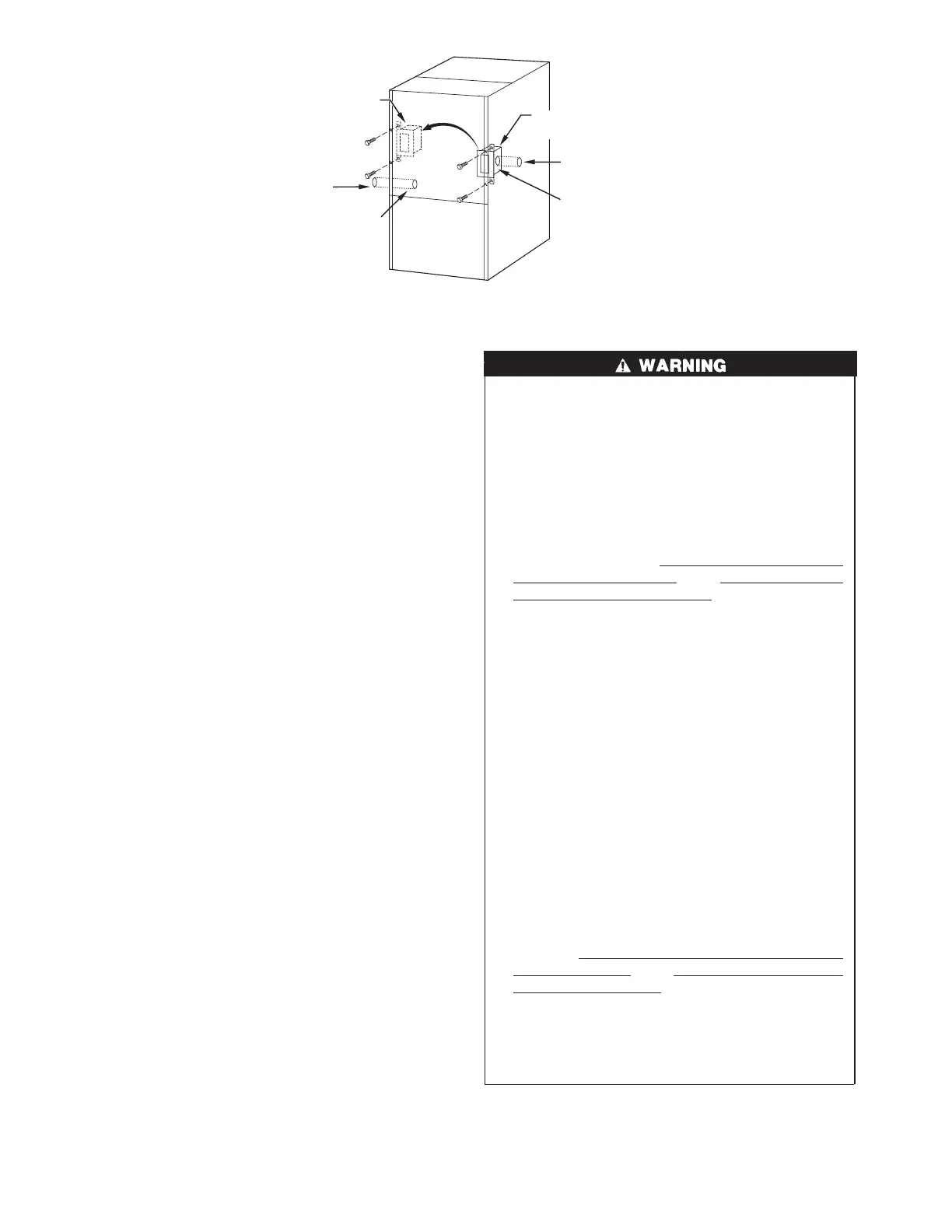
→ Fig. 35—Relocating J-Box
A05058
FACTORY
INSTALLED
LOCATION
ALTERNATE
FIELD
LOCATION
POWER ENTRY HOLE
FILLER PLUG (FACTORY-
SUPPLIED LOOSE PARTS BAG)
UNUSED 7/8-IN. DIAMETER
POWER ENTRY HOLES
UNUSED 7/8-IN. DIAMETER
POWER ENTRY HOLES
POWER ENTRY HOLE
FILLER PLUG (FACTORY-
SUPPLIED LOOSE PARTS BAG)
28
→
→
→
→