EXAMPLE:
An 080-12 size furnace located in Indianapolis, elevation
650 ft above sea level, could be installed as either a direct
vent/2-pipe system that requires 3 elbows and 32 ft of vent
pipe, along with 5 elbows and 34 ft of combustion-air pipe
OR a non-direct vent/1-pipe system that requires 3 elbows
and 32 ft vent pipe.
For a direct vent/2-pipe system, Table 12 indicates this
application would allow a 2-in. diameter vent pipe, but
require a 2-1/2 in. diameter combustion air pipe. According
to Table 12, 2-in. diameter pipe is good for 35 ft with 3
elbows, but only 30 ft with 5 elbows. Therefore, 2-1/2 in.
diameter pipe must be used for both vent and combustion-
air pipes since larger required diameter must always be
used for both pipes.
For a non-direct vent/1-pipe system, Table 12 indicates that
this application would allow a 2-in. diameter vent pipe.
If same installations were in Albuquerque, elevation 5250 ft
above sea level:
For a direct vent/2-pipe system, Table 12 indicates that
2-1/2 in. diameter vent pipe and combustion-air pipe are
required.
For a non-direct vent/1-pipe system, Table 12 indicates that
2-1/2-in. diameter vent pipe is required.
If same applications are to be installed at 5001- to 6000 ft
elevation:
For a direct vent/2-pipe system, 2-in. pipe is only good for
23 ft (with 3 elbows) and 17 ft (with 5 elbows). Therefore,
2-1/2 in. diameter combustion air and vent pipe must be
used.
For a non-direct vent/1-pipe system, a 2-in. diameter pipe is
only good for 23 ft with 3 elbows. A 2-1/2-in. diameter vent
pipe must be used.
VENT TERMINATION
General
Combustion-air (direct vent/2-pipe system only) and vent pipe
must terminate outside structure, either through sidewall or roof.
For vent termination clearance, refer to Table 8 for Direct
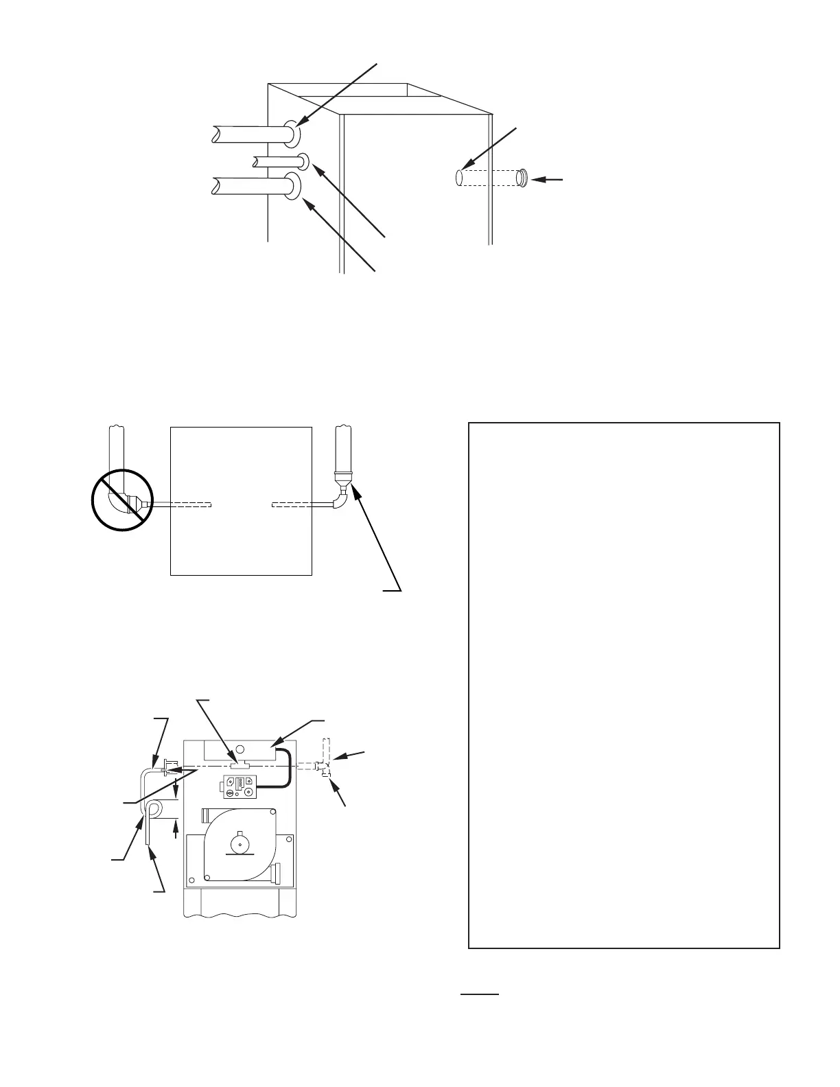
Fig. 40—Pipe Grommets and Entry Hole Filler Plug Installation
COMBUSTION-AIR PIPE GROMMETS
GAS LINE GROMMET
GAS LINE
COMBUSTION
-AIR PIPE
VENT PIPE
VENT PIPE GROMMET
UNUSED 1/2 -IN.
DIAMETER GAS
CONN. HOLE
GAS LINE ENTRY
HOLE FILLER PLUG
NOTE: PIPE GROMMETS AND ENTRY HOLE FILLER
PLUGS ARE INCLUDED IN FACTORY-SUPPLIED
LOOSE PARTS BAG
A05057
Fig. 41—Combustion-Air and Vent Pipe Diameter
Transition Location and Elbow Configuration
A93034
FURNACE
PIPE DIAMETER
TRANSITION IN
VERTICAL SECTION
NOT IN
HORIZONTAL
SECTION
→ Fig. 42—Air Intake Housing Plug Fitting Drain
A05093
COMBUSTION-AIR
PIPE (DIRECT
VENT/2 PIPE)
BURNER
BOX
COMBUSTION – AIR
INTAKE HOUSING
3/8 ID TUBE
TRAP
TO OPEN
DRAIN
3/16
DRILL
4″MIN
COMBUSTION-AIR
PIPE (NON-DIRECT
VENT/1-PIPE)
39
→
→
→