high-heat gas valve solenoid GV-HI is de-energized. When
the inducer motor IDM reduces pressure sufficiently, the
high-heat pressure switch HPS will open. The gas valve
solenoid GV-M will remain energized as long as the low-heat
pressure switch LPS remains closed. The blower motor
BLWM will transition to low-heat airflow five seconds after
the R to W2 circuit opens.
Step 3—Cooling Mode
The thermostat ″calls for cooling″.
1. Single-Speed Cooling
The thermostat closes the R to G-and-Y circuits. The R to Y
circuit starts the outdoor unit, and the R to G-and-Y/Y2
circuits start the furnace blower motor BLWM on cooling
airflow. Cooling airflow is based on the A/C selection shown
in Table 1 and 1a.
The electronic air cleaner terminal EAC-1 is energized with
115 vac when the blower motor BLWM is operating.
When the thermostat is satisfied, the R to G-and-Y circuits are
opened. The outdoor unit will stop, and the furnace blower
motor BLWM will continue operating at cooling airflow for
an additional 90 seconds. Jumper Y/Y2 to DHUM to reduce
the cooling off-delay to 5 seconds. (See Fig. 2 in Appendix.)
2. Single-Stage Thermostat and Two-Speed Cooling
(Adaptive Mode)
This furnace can operate a two-speed cooling unit with a
single-stage thermostat because the furnace control CPU
includes a programmed adaptive sequence of controlled op-
eration, which selects low-cooling or high-cooling operation.
This selection is based upon the stored history of the length of
previous cooling period of the single-stage thermostat.
NOTE: The air conditioning relay disable jumper ACRDJ must
be connected to enable the adaptive cooling mode in response to a
call for cooling. (See Fig. 2 in Appendix.) When in place the
furnace control CPU can turn on the air conditioning relay ACR to
energize the Y/Y2 terminal and switch the outdoor unit to
high-cooling.
The furnace control CPU can start up the cooling unit in
either low- or high-cooling. If starting up in low-cooling, the
furnace control CPU determines the low-cooling on-time
(from 0 to 20 minutes) which is permitted before switching
to high-cooling.
If the power is interrupted, the stored history is erased and
the furnace control CPU will select low-cooling for up to 20
minutes and then energize the air conditioning relay ACR to
energize the Y/Y2 terminal and switch the outdoor unit to
high-cooling, as long as the thermostat continues to call for
cooling. Subsequent selection is based on stored history of
the thermostat cycle times.
The wall thermostat ″calls for cooling″, closing the R to
G-and-Y circuits. The R to Y1 circuit starts the outdoor unit
on low-cooling speed, and the R to G-and-Y1 circuits starts
the furnace blower motor BLWM at low-cooling airflow
which is the true on-board CF selection as shown in Table 1
and 1a.
If the furnace control CPU switches from low-cooling to
high-cooling, the furnace control CPU will energize the air
conditioning relay ACR. When the air conditioning relay
ACR is energized the R to Y1-and-Y2 circuits switch the
outdoor unit to high-cooling speed, and the R to G-and-Y1-
and-Y/Y2 circuits transition the furnace blower motor
Table 1—Cooling Tonnage vs. Airflow (CFM)
AIR CONDITIONING TONS
(12,000 BTU/HR)
AIRFLOW
(CFM)
040, 060, AND 3T-080 MODEL 5T-080 AND 100 MODEL 120 MODEL
1-1/2 525 X
2 700 X X X
2-1/2 875 X X X
3 1050 X X X
3-1/2 1225 X X X
4 1400 X X
5 1750 X X
6 2100 X
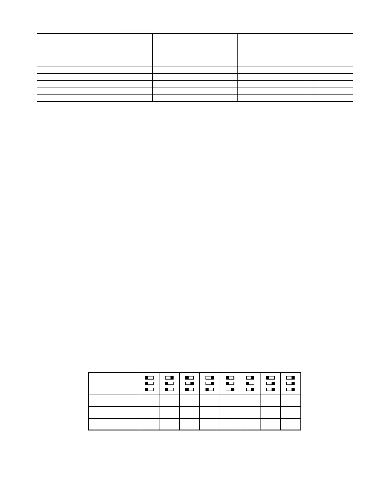
Table 1a—A/C or CF Airflow Selection Chart
A03083
A/C OR CF AIRFLOW SELECTION CHART
BASED ON 350 CFM/TON
MODEL
SIZE
040,060, 3T-080
5T-080, 100
120
DEF. 525
2
700 875 1050
1
1225 1225 1225
DEF. 700
2
875 1050 1225 1400 1750
1
1750
DEF. 700 875
2
1050 1225 1400 1750
1
2100
1. DEFAULT A/C AIRFLOW WHEN A/C SWITCHES ARE IN OFF POSITION
2. DEFAULT CONT. FAN AIRFLOW WHEN CF SWITCHES ARE IN OFF POSITION
5
 Loading...


