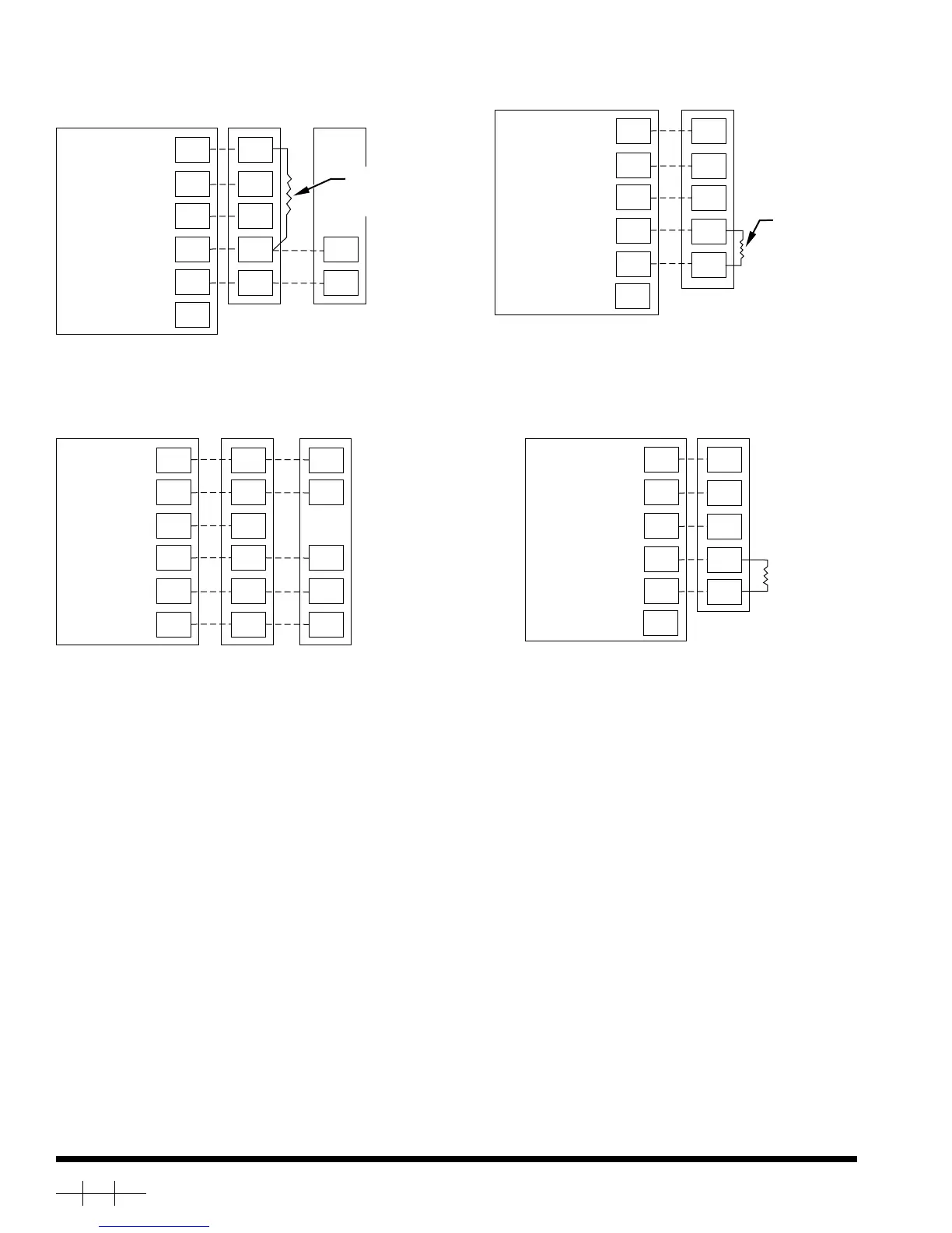
*WIRING DIAGRAM NOTES
1. If "power stealing" method is used, leave C terminal disconnected between thermostat and equipment and add the supplied 270 ohm load
resistor as shown.
2. Power stealing method may not be used with the Two-Zone system. In addition, the supplied 270 ohm load resistor MUST always be
connected between Y1 and C at Two-Zone input as shown.
Fig. 4—Typical Heat Pump
A98217
HEAT STAGE 2
FAN
24 VAC HOT
24 VAC COMM
W
O
G
R
C
Y
W
O
G
R
C
Y
W
O
R
C
Y
HEAT PUMP
THERMOSTAT
SINGLE-SPEED
HEAT PUMP
TYPICAL
FAN COIL
VALVE
REVERSING
HEAT/COOL
STAGE 1
Fig. 2—Typical Air Conditioner
A99154
HEATING
FAN
24 VAC HOT
24 VAC COMM
COOLING
N/A
W
G
R
C
Y
W
G
R
C
Y
C
Y
AC
THERMOSTAT
SINGLE-SPEED
AIR CONDITIONER
TYPICAL
FAN COIL/
FURNACE
270 Ω, 10 W *
RESISTOR
(SUPPLIED)
* See note 1
*
O
Fig. 5—Two-Zone with Air Conditioner
A99116
HEATING
FAN
24 VAC HOT
24 VAC COMM
COOLING
N/A
W
G
R
C
W1
G
R
C
Y
Y
1
AC
THERMOSTAT
TWO-ZONE
THERMOSTAT
INPUT
270 Ω, 10 W *
RESISTOR
(SUPPLIED)
* See note 2
*
O
Fig. 3—Typical Heat Only
A99115
HEATING
FAN
24 VAC HOT
24 VAC COMM
COOLING
N/A
W
G
R
C
Y
W
G
R
C
Y
AC
THERMOSTAT
TYPICAL
FAN COIL/
FURNACE
270 Ω, 10 W *
RESISTOR
(SUPPLIED)
*
* See note 1
O
Copyright 1999 CARRIER Corp. • 7310 W. Morris St. • Indianapolis, IN 46231 tstt22si
Manufacturer reserves the right to discontinue, or change at any time, specifications or designs without notice and without incurring obligations.
Book 1 4
Tab misc. misc.
PC 101 Catalog No. 03TS-TA16 Printed in U.S.A. Form TSTAT-22SI Pg 4 8-99 Replaces: TSTAT-21SI