59SC2E: Installation, Start-up, Operating and Service and Maintenance Instructions
Manufacturer reserves the right to change, at any time, specifications and designs without notice and without obligations.
42
A11313A
Representative drawing only, some models may vary.
DOWNFLOW VERTICAL
Fig. 55 – Downflow Configurations (Appearance may vary)
See “Notes for Venting Options”
A11327A
Representative drawing only, some models may vary.
HORIZONTAL LEFT-VERTICAL VENT CONFIGURATION
A11328A
Representative drawing only, some models may vary.
HORIZONAL LEFT-LEFT VENT CONFIGURATION
A11329A
Representative drawing only, some models may vary.
HORIZONTAL LEFT-RIGHT VENT CONFIGURATION
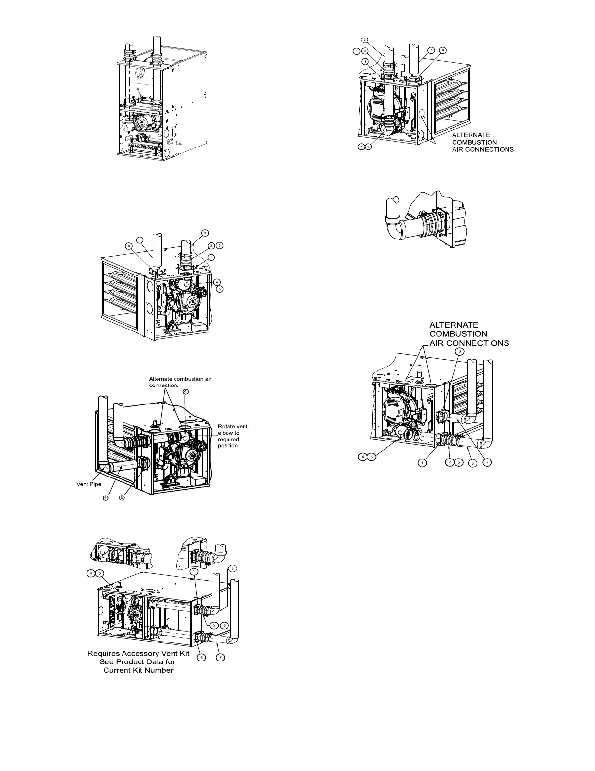
Fig. 56 – Horizontal Left (Appearance may vary)
See “Notes for Venting Options”
A11337
Representative drawing only, some models may vary.
HORIZONTAL RIGHT-VERTICAL VENT CONFIGURATION
A11336
Representative drawing only, some models may vary.
HORIZONTAL RIGHT-LEFT VENT CONFIGURATION
A11335
Representative drawing only, some models may vary.
HORIZONTAL RIGHT-RIGHT VENT CONFIGURATION
Fig. 57 – Horizontal Right (Appearance may vary)
See “Notes for Venting Options”
Notes for venting options
1. Attach vent pipe adapter with gasket to furnace casing.
2. Align notches in rubber coupling over standoffs on adapter. Slide
clamps over the coupling.
3. Slide vent pipe through adapter and coupling into vent elbow.
4. Insert vent pipe into vent elbow.
5. Torque all clamps 15 lb.-in.
6. Attach combustion air pipe adapter with gasket to furnace.
7. Attach combustion air pipe to adapter with silicone. Pilot drill a
1/8-in. hole in adapter and secure with a #7 x 1/2-in. sheet metal
screw.
Requires Accessory Internal Vent Kit.
See Product Data for current kit number.
Additional coupling required from
transition to polypropylene piping.