21
Air
gap
here
Open
standpipeLQKLJK
PLQLPXP
for
coilor
humidifier
drain
TEE
(1/2”
CPVC
to
3/4”
PVC
adapter
from
loose
parts
bag.)
To
open
drain
&RLORUKXPLGLILHUGUDLQ
ZKHQXVHG
+
+
+
Condensing
Furnace
-
-
-
-
-
ÄÄÄÄÄÄÄÄÄÄ
ÄÄÄÄÄÄÄÄÄÄ
ÄÄÄÄÄÄÄÄÄÄ
ÄÄÄÄÄÄÄÄÄÄ
ÄÄÄÄÄÄÄÄÄÄ
ÄÄÄÄÄÄÄÄÄÄ
ÄÄÄÄÄÄÄÄÄÄ
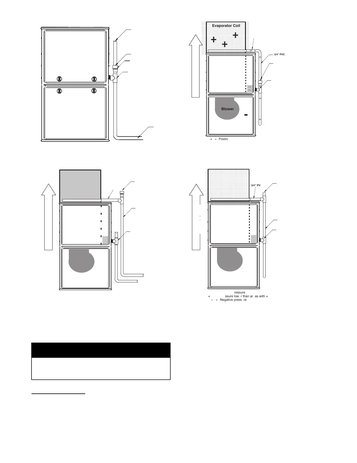
Evaporator Coil
+
+
+
< +
< +
< +
+
Blower
-
3/4”
PVC
3/4
3/4
3/4
3/4
+ = Positive pressure
< + = Pressure lower than areas with +
ï = Negative pressure
+
3/4”
PVC
DIRECTION
OF
AIRFLOW
+
+
+
3/4
Open standpipeLQKLJKPLQLPXP
Air
gap
required
when
another
drain
is
connected
to
furnace
drain.
+
TEE
(1/2”
CPVC
to
3/4”
PVC
adapter
from
loose
parts
bag.)
+
+
+
Condensing
Furnace
ï
ï
ï
ï
ï
Evaporator Coil
+
+
+
< +
< + < +
+
Blower
ï
3/4” PVC
3/4
1/2”CPVCorlarger*
+
= Positive pressure
< +
= Pressure lower than areas with +
( = Negative pressure
+
3/4” PVC
DIRECTION OF AIRFLOW
+
+
+
+
3/4
3/4
3/4
3/4
Open
standpipe
(Optional
when coil drain
is
not
connected to
furnace
drain.)
Recommend “T” fitting
standpipe of same
diameteror larger
H[WHQGLQJXSZDUG
ZLWKPLQLPXPLQFKhigh
+
+
+
Condensing
Furnace
-
-
-
-
-
Evaporator
ÄÄÄÄÄÄÄÄÄ
Coil
ÄÄÄÄÄÄÄÄÄ
+
ÄÄÄÄÄÄÄÄÄ
+
ÄÄÄÄÄÄÄÄÄ
+
ÄÄÄÄÄÄÄÄÄ
ÄÄÄÄÄÄÄÄÄ
+
ÄÄÄÄÄÄÄÄÄ
< +
< +
< +
+
Blower
-
3/4”
PVC
3/4
3/4
3/4
3/4
3/4
3/4
+ = Positive pressure
< + = Pressure lower than areas with +
ï = Negative pressure
3/4”
PVC
Open
standpipe
(Optional
when
coil
drain
is
not
connected
to
furnace
drain.)
TEE
(1/2”
CPVC
to
3/4”
PVC
adapter
from
loose
parts
bag.)
DIRECTIONOFAIRFLOW
A170135
Fig. 18 -- Example of Field Drain Attachment
INSTALLATION
Cabinet air leakage is less than 2% at 1.0 in. W.C. Cabinet air
leakage is less than 1.4% at 0.5 in. W.C. when tested in accor-
dance with ASHRAE Standard 193.
NOTICE
Upflow Installation
NOTE: The furnace must be pitched as shown in Fig. 21 for
proper condensate drainage.
Supply Air Connections
For a furnace not equipped with a cooling coil, the outlet duct shall
be provided with a removable access panel. This opening shall be
accessible when the furnace is installed and shall be of such a size
that the heat exchanger can be viewed for possible openings using
light assistance or a probe can be inserted for sampling the air
stream. The cover attachment shall prevent leaks.
Connect supply--air duct to flanges on furnace supply--air outlet.
Bend flange upward to 9 0_ with wide duct pliers. See Fig. 19.
The supply-- air duct must be connected to ONLY the furnace
supply-- outlet-- air duct flanges or air conditioning coil casing
(when used). DO NOT cut main furnace casing side to attach
supply air duct, humidifier, or other accessories. All supply--side
accessories MUST be connected to duct external to furnace main
casing.

 Loading...


