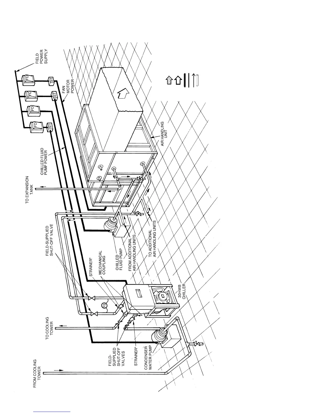
Fig. 13 — Typical Piping with Fluid-Cooled 30HWB Unit Shown
NOTES:
1. Chiller must be installed
levelly
to maintain proper compressor oil return.
2. Wiring and piping shown are general points-of-connection guides only and are not intended for a specific installation. Wiring and piping
shown are for a quick overview of system and are not in accordance with recognized standards.
3. All wiring must comply with applicable local and national codes.
4. All piping must follow standard piping techniques. Refer to Carrier System Design Manual or appropriate ASHRAE (American Society
of Heating, Refrigeration, and Air Conditioning Engineers) handbook for details.
5. See Table 3 on page 17 for minimum system fluid volume. This system may require the addition of a holding tank to ensure adequate
volume.
LEGEND
Airflow Through Condenser
Airflow Through Air
Handling Unit
Power Wiring
Control Wiring
Chilled Water Piping
ST — Field-Supplied Starter
FD — Field-Supplied Disconnect
FS — Field-Supplied Differential
Flow Switch
*Field Supplied.
14