Do you have a question about the Carrier 69NT40-541-505 and is the answer not in the manual?
General safety precautions for installation and service procedures.
Procedures for immediate medical attention after injury.
Safety measures to be observed during unit operation.
Safety measures to be observed during unit maintenance.
Explanation of hazard labels (DANGER, WARNING, CAUTION).
Overview of the refrigeration unit series and its design.
Location and purpose of unit identification plates.
Detailed descriptions of unit components and their functions.
Descriptions of optional equipment that can be fitted to the base unit.
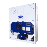
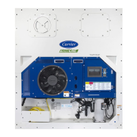
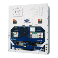
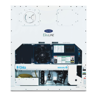
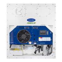
Overall description of the refrigeration unit front section.
Key technical data for the refrigeration system.
Electrical specifications for unit components.
Devices protecting the unit and unsafe conditions.
Explanation of the refrigerant flow through the system.
Overview of the Micro-Link 3 system components.
Functions of the custom designed controller software.
Sequences for cooling, heating, and defrost operations.
Modes to protect the unit from damage.
Explanation of Compressor-Cycle Perishable Cooling.
How the controller generates and displays alarms.
Automatic testing of unit components.
Functions for recording and retrieving unit data.
List of configurable variables for the controller.
List of codes for accessing controller functions.
Descriptions and troubleshooting for controller alarms.
Codes and descriptions for pre-trip tests.
Pre-operation checks of the unit and container.
Procedures for connecting the unit to power sources.
Adjusting airflow for commodities.
Connecting a plug for remote monitoring circuits.
Procedures for starting and stopping the unit.
Checks to perform after starting the unit.
Performing automatic and manual pre-trip tests.
Checking temperature probe accuracy and disagreement.
Using the bypass switch for controller failure.
Common causes and remedies for startup issues.
Causes and solutions for prolonged cooling operation.
Troubleshooting insufficient cooling performance.
Diagnosing issues with heating or insufficient heating.
Causes and solutions for heating that does not terminate.
Troubleshooting defrost issues.
Identifying and resolving abnormal pressure conditions.
Diagnosing and fixing unusual noises or vibrations.
Troubleshooting issues with the microprocessor.
Addressing problems with evaporator air circulation.
Troubleshooting issues with the TXV.
Diagnosing problems with the autotransformer.
Overview of service procedures provided in the section.
Use of the manifold gauge set for system service.
Function and use of service valves.
Procedure for pumping down the unit for service.
Methods for detecting refrigerant leaks.
Procedures for removing moisture from the system.
Procedures for adding refrigerant to the system.
Service procedures for the compressor.
Service procedures for the high pressure switch.
Service procedures for the condenser coil.
Service procedures for the condenser fan and motor.
Checking and replacing the filter-drier.
Service procedures for the evaporator coil and heater assembly.
Service procedures for the evaporator fan and motor.
Cleaning the evaporator section for corrosion.
Service procedures for the thermostatic expansion valve.
Procedures for the suction modulation valve.
Using codes for manual SMV operation.
Troubleshooting autotransformer issues.
Service procedures for the controller module.
Service procedures for temperature sensors.
Replacing and calibrating the vent position sensor.
Procedures for maintaining painted surfaces.
Installing the communications interface module.
Introduction to the electrical schematics and wiring diagrams.
| Brand | Carrier |
|---|---|
| Model | 69NT40-541-505 |
| Category | Refrigerator |
| Language | English |
