7–21 T-368
7.20.2 Controller Troubleshooting
A group of test points (TP) (see Figure 7.25) are pro-
vided on the controller for troubleshooting electrical cir-
cuits (see schematic diagram, Section 8). A
description of the test points follows:
Use a digital voltmeter to measure AC volt-
age between TPs and ground (TP9), except
for TP8.
TP 1 − NA
TP 2 − This test point enables the user to check if the
internal protector for the compressor motor (IP-CP) or
high pressure switch is open.
TP 3 − This test point enables the user to check if the
water pressure switch (WP) contact is open or closed.
TP 4 − This test point enables the user to check if the
internal protector for the condenser fan motor (IP-CM)
is open or closed.
TP 5 − This test point enables the user to check if the
internal protectors for the evaporator fan motors (IP-
EM1 or IP-EM2) are open or closed.
TP 6 − This test point enables the user to check if the
controller water tank heater relay (TQ) is open or
closed.
TP 7 − This test point is not used in this application.
TP 8 − This test point is not applicable to the units cov-
ered herein.
TP 9 − This test point is the chassis (unit frame) ground
connection.
TP 10 − This test point enables the user to check if the
heat termination thermostat (HTT) contact is open or
closed.
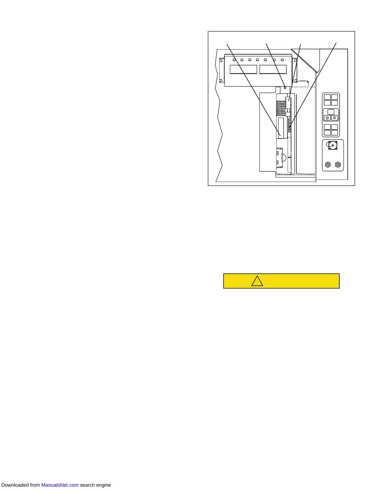
Figure 7.25 Controller Section of the Control Box
1. Controller Software Programming Port
2. Mounting Screw
3. Controller
4. Test Points
- - - - -
7.20.3 Controller Programming Procedure
To load new software into the module, the program-
ming card (PCMIA) is inserted into the programming/
software port.
The unit must be OFF whenever a pro-
gramming card is inserted or removed
from the controller programming port.
Loading operational software:
1. Turn unit OFF via start-stop switch (ST).
2. Insert software/programming card containing
the following (example) files into the program-
ming/software port (see Figure 7.25):
menuDDMM.ml3 − This file allows the user
to select a file/program to upload into the
controller.
cfYYMMDD.ml3 − Multi-configuration file.
3. Turn unit ON via start-stop switch (ST).
4. The display module will display the message ruN
COnFG. If a defective card is being used, the dis-
play will blink the message “bAd CArd.” Turn
start-stop switch OFF and remove the card.
Downloaded from ManualsNet.com search engine

 Loading...


