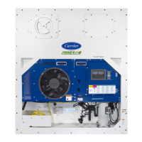
Do you have a question about the Carrier 69NT40-561-399 and is the answer not in the manual?
Covers general safety notices, first aid, operating, and maintenance precautions.
Describes key features of the refrigeration unit and available optional equipment.
Details the front, evaporator, compressor, condenser, control box, and communication module sections.
Provides refrigeration and electrical system data, along with safety and protective devices.
Explains the standard and economized refrigeration circuits.
Explains the microprocessor system, keypad, display, and controller functions.
Details controller software, sequences, modes of operation, and protection modes.
Covers controller alarms, pre-trip diagnostics, and probe diagnostics.
Explains DataCORDER software, settings, functions, and configurations.
Lists and describes controller configuration variables and pre-trip test codes.
Outlines pre-loading inspections and procedures for connecting power.
Provides instructions for adjusting upper and lower fresh air makeup vents.
Details eAutoFresh system operation, modes, and start-up procedures.
Covers starting, stopping the unit, start-up inspections, pre-trip diagnosis, and probe diagnostics.
Addresses problems with unit starting, stopping, and continuous operation.
Troubleshoots insufficient cooling, heating, or lack thereof, and defrost problems.
Addresses abnormal pressures, noise, vibrations, microprocessor, airflow, and component malfunctions.
Covers manifold gauge use, service connections, pump down, leak checking, evacuation, and refrigerant charge.
Details compressor replacement and high pressure switch service.
Covers service for condenser coil, fan motor, and filter drier.
Details service for evaporator coil, heater, fan assembly, expansion valves, and solenoid valves.
Addresses troubleshooting and replacement of digital unloader and loader valves, and controller service.
Covers autotransformer checks and temperature sensor service procedures.
Details service for vent position sensor and eAutoFresh drive system.
Covers communications module installation and painted surface maintenance.
Introduces the electrical schematics and wiring diagrams provided in the section.
| Brand | Carrier |
|---|---|
| Model | 69NT40-561-399 |
| Category | Refrigerator |
| Language | English |

