T-365 4–26
4.10 CONTROLLER FUNCTION CODES
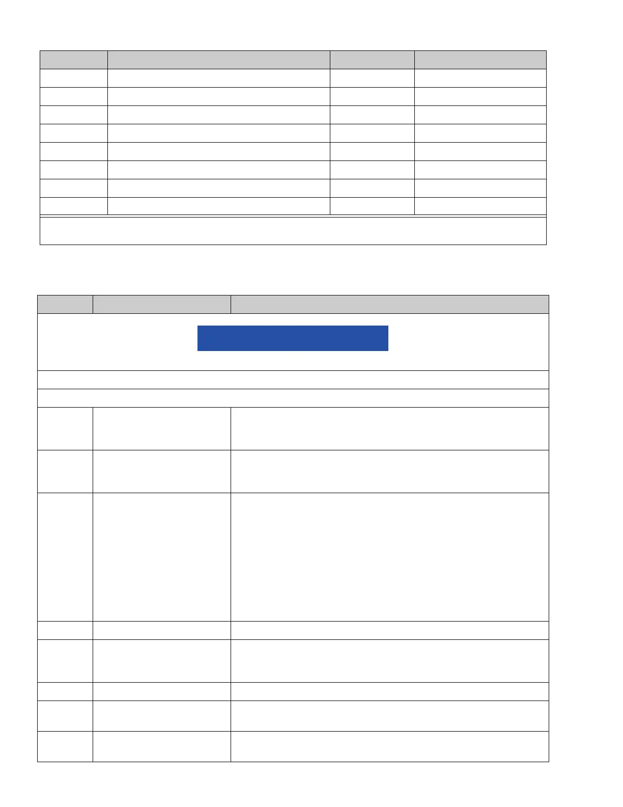
CnF64 Enable Fan Pulsing Logic 0-in 1-out
CnF66 High Speed Evaporator Fan Option 0-off 1-on
CnF67 Air Heaters 0-out 1-in
CnF68 Enable Default Pulsing Temperature 0-out 1-in
CnF70 Enable XtendFRESH Logic 0-out 1-in
CnF71 XtendFRESH Pretrip/Trip Start Default State OFF On
CnF72 Enhance Economy Mode OFF On
CnF73 Custom Defrost Mode 0-out 1-in
Table 4–3 Controller Function Codes
CODE # TITLE DESCRIPTION
If the function is not applicable, the display will read “-----”
Display Only Functions - Cd01 through Cd26 are display only functions.
Display Only Functions
Cd01 Digital Unloader Valve
Closed (%)
Displays the DUV percent closed. The right display reads 100% when
the valve is fully closed. The valve will usually be at 10% on start up of
the unit except in very high ambient temperatures.
Cd03 Compressor Motor Current The current sensor measures current draw in lines L1 & L2 by all of the
high voltage components. It also measures current draw in compres-
sor motor leg T3. The compressor leg T3 current is displayed.
Cd04
Cd05
Cd06
Line Current,
Phase A
Line Current,
Phase B
Line Current,
Phase C
The current sensor measures current on two legs. The third unmea-
sured leg is calculated based on a current algorithm. The current mea-
sured is used for control and diagnostic purposes. For control
processing, the highest of the Phase A and B current values is used for
current limiting purposes. For diagnostic processing, the current draws
are used to monitor component energization. Whenever a heater or a
motor is turned ON or OFF, the current draw increase/reduction for that
activity is measured. The current draw is then tested to determine if it
falls within the expected range of values for the component. Failure of
this test will result in a Pre-trip failure or a control alarm indication.
Cd07 Main Power Voltage The main supply voltage is displayed.
Cd08 Main Power Frequency The value of the main power frequency is displayed in Hertz. The fre-
quency displayed will be halved if either fuse F1 or F2 is bad (alarm
code AL21).
Cd09 Ambient Temperature The ambient sensor reading is displayed.
Cd10 Evaporator Temperature
Sensor
Evaporator temperature sensor reading is shown on the right display.
Cd11 Compressor Discharge Tem-
perature
Compressor discharge temperature sensor reading, using compressor
dome temperature, is displayed.
Table 4–2 Controller Configuration Variables (Continued)
CONFIG. # TITLE DEFAULT OPTION
Note: Configuration numbers not listed are not used in this application. These items may appear when loading T-365
3-20 configuration software to the controller but changes will not be recognized by the controller programming.

 Loading...


