K
Kevin GutierrezAug 7, 2025
What does E1 mean on Carrier A07048 Thermostat?
- VVincent WilliamsAug 8, 2025
If the Display Module and the Equipment Control Module cannot communicate via two--wire connection, an E1 will be displayed.
What does E1 mean on Carrier A07048 Thermostat?
If the Display Module and the Equipment Control Module cannot communicate via two--wire connection, an E1 will be displayed.
How to troubleshoot Carrier A07048 Thermostat display module not powering up?
If your Carrier Thermostat's display module doesn't power up, begin by checking the Rc/Rh and C terminals to ensure they are receiving 24VAC. If 24VAC is present, then check the voltage between Vg and V+. If voltage is present, verify the wiring polarity is correct, as the display won't power up if the polarity is reversed.
What to do if Carrier A07048 Thermostat Control’s internal memory fails?
If the Thermidistat Control's internal memory fails, you should replace the Thermidistat Control.
How to fix Carrier A07048 Thermostat display module if it doesn’t power up?
If the display module doesn’t power up after power is applied, check the Rc/Rh and C terminals for 24VAC. If 24VAC is present, check the voltage between Vg and V+. This voltage will be approximately 12--20VDC. If voltage is present, check the polarity to make sure it is wired correctly. The display will not power up if polarity is reversed.
What to do if Carrier A07048 Control cannot properly read humidity?
If the Thermidistat Control cannot properly read humidity, replace the Thermidistat Control.
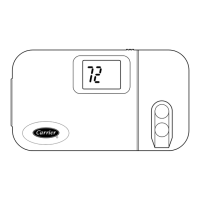
| Stages | 1 Heat/1 Cool |
|---|---|
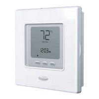
| Programmable | No |
| Filter Change Alert | No |
| Type | Non-Programmable |
| Compatibility | Single Stage Systems |
| Power Source | 24VAC |
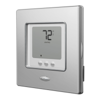
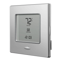
Details the features and capabilities of the programmable model.
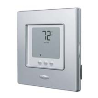
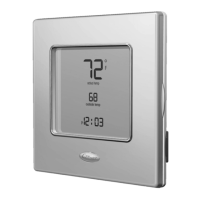
Details the features and capabilities of the non-programmable model.
Explains safety alert symbols and signal words like DANGER, WARNING, and CAUTION.
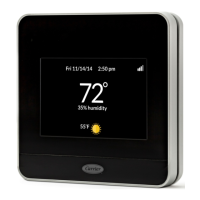
Describes the Carrier Performance Series Thermidistat Control features and configurations.
Details the 24VAC power supply and transformer connections for proper operation.
Discusses programmable and non-programmable models and their applications.
Explains connections for humidification and dehumidification equipment.
Covers installation and use of outdoor and remote room temperature sensors.
Explains the benefits and requirements of a two-piece installation setup.
Provides specifications for wire gauge and length for proper installation.
Warns about potential damage to the control from improper wiring or installation.
Provides essential notes on mounting, wiring, and handling the thermostat.
Specifies ideal and inadvisable locations for mounting the thermostat.
Reinforces safety warnings regarding turning off power before installation.
Details how to activate installer test mode for equipment operation testing.
Explains the process for testing heating and cooling stages and indicators.
Describes how to test the fan operation and the G output.
Guides on setting the system mode and default Energy Star settings.
Explains compressor, cycle, and staging timers for system operation.
Details defrost operation in Hybrid Heat systems and defrost detection.
Specifies minimum run times for stages to prevent short cycling.
Describes equipment on indicators, humidify/dehumidify indicators.
Explains auto changeover logic and emergency heat mode operation.
Addresses display not powering up and checks for 24VAC and Vg/V+ voltage.
Details issues related to Option 01 configuration and pigtail wiring.
Lists and explains error codes (--, E1, E2, E3, E4, E5) and their meanings.
Shows wiring connections between display and equipment control modules.
Illustrates wiring for a specific fan coil and heat pump configuration.
Provides a general wiring diagram for fan coil and heat pump systems.
Details wiring for fan coil with auxiliary connection.
Shows wiring for fan coil and 1-stage air conditioner.
Illustrates wiring for a typical fan coil used for cooling only.
Shows wiring for furnace and heat pump systems.
Details wiring for furnace and air conditioner systems.
Section to record hardware settings like sealing the wall hole.
Section to record mode, heating/cooling setpoints, and fan settings.
Section for recording temperature settings for different modes.
Section for recording programmable schedule settings for different days.