iii
T--30404/08
TABLE OF CONTENTS Continued:
5.13 SERVICING THE LIQUID LINE SOLENOID VALVE 5--6.......................................
5.13.1 Coil Replacement 5--6.................................................................
5.13.2 Internal Part Replacement 5--6..........................................................
5.13.3 Replace Entire Valve 5--6...............................................................
5.14 SERVICE VALVES 5--7....................................................................
5.15 REPLACING RETURN AIR FILTERS 5--7...................................................
5.16 THERMOSTATIC EXPANSI ON VALVE 5--8..................................................
5.16.1 Valve Replacement 5-- 8................................................................
5.16.2 Superheat Measurement 5--9...........................................................
ELECTRICAL 6--1................................................................................
6.1 INTRODUCTION 6--1.....................................................................
LIST OF FIGURES
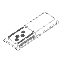
Figure 1--1 AC310/350 Rooftop Units 1--2...........................................................
Figure 1--2 Condensing Section Components (AC310 -- Dual Loop -- GEN I) 1--3..........................
Figure 1--3 Condensing Section Components (AC350 Single Loop -- GEN II) 1--4.........................
Figure 1--4 Evaporator Section Components (AC310 --Dual Loop -- GEN I) 1--5...........................
Figure 1--5 Evaporator Section Components (AC350 Single Loop -- GEN II) 1--6..........................
Figure 1--6 Refrigerant Flow Diagram -- Cooling (Dual Loop) 1--9...........................................
Figure 1--7 Flow Diagram -- Heating 1--10...............................................................
Figure 1--8 Refrigerant Flow Diagram, Cooling (Single Loop) AC350 1--11.................................
Figure 1--9 Sheet 1 -- Electrical Control Board (280P) 1--12.............................................
Figure 1--9 Sheet 2 Legend 1--13....................................................................
Figure 1--10 AC350 With BT324 Control 1--14.........................................................
Figure 1--11 Motor Fault Board (Optional) 1--15........................................................
Figure 2.1 Control Switches (T ypical) 2--1..............................................................
Figure 2.2 280P / 282P Thermostat 2--3.............................................................
Figure 3--1 Bus Dash With A/C Switch & BT324 CSDD Controller 3--1...................................
Figure 3--2 BT324 CSDD Controller 3--2.............................................................
Figure 5--1 Manifold Gauge Set (R--134a) 5--2........................................................
Figure 5--2 In--Line Service Connections 5--3.........................................................
Figure 5--3 Checking High Pressure Switch 5--4......................................................
Figure 5--4 Filter--Drier Removal 5--5................................................................
Figure 5--5 Heat Valve 5--6........................................................................
Figure 5--6 Liquid Line Solenoid Valve 5--7...........................................................
Figure 5--7 Service Valve R134a (High Side) 5--7.....................................................
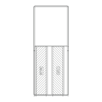
Figure 5--8 Return Air Grill Assembly With Air Filter Showing 5--7.......................................
Figure 5--9 Diffuser and Filter Element 5--8..........................................................
Figure 5--10 Filter , Diffuser and Composit Frame 5--8.................................................
Figure 5--11 Return Air Grill Assembly With Diffuser And Composit Frame Showing 5--8...................
Figure 5--12 Thermostatic Expansion Valve 5--8......................................................
Figure 5--13 Thermostatic Expansion Valve Bulb and Thermocouple 5--9.................................
Figure 6--1 System Controls (Typical) 6--2...........................................................
Figure 6--2 Manual Controls With Manual Reheat Control (Sheet 1) 6--3.................................
Figure 6--3 Manual Controls With Manual Reheat Control (Sheet 2) 6--4.................................