Manufacturer reserves the right to discontinue, or change at any time, specifications or designs without notice and without incurring obligations.
Catalog No. 04-53500286-01 Printed in U.S.A. Form 50HQP-VQP-4SI Pg 1 10-2020 Replaces: 50HQP-VQP-2SI
Installation, Start-Up, and
Service Instructions
CONTENTS
Page
SAFETY CONSIDERATIONS . . . . . . . . . . . . . . . . . . . 2
GENERAL . . . . . . . . . . . . . . . . . . . . . . . . . . . . . . . . . . . 2
PRE-INSTALLATION . . . . . . . . . . . . . . . . . . . . . . . . . . 3
• INSPECTION
• STORAGE
INSTALLATION . . . . . . . . . . . . . . . . . . . . . . . . . . . . . . 3
Step 1 — Check Jobsite . . . . . . . . . . . . . . . . . . . . . . . 3
• HO
RIZONTAL UNITS (50HQP)
• VERTICAL UNITS (50VQP)
• INSTALLATION GUIDELINES (ALL UNITS)
Step 2 — Check Unit . . . . . . . . . . . . . . . . . . . . . . . . . . 3
• INSPECT UNIT
Step 3 — Locate Unit . . . . . . . . . . . . . . . . . . . . . . . . 12
Step 4 — Mount the Unit . . . . . . . . . . . . . . . . . . . . . . 12
• MOUNTING VERTICAL UNITS
• MOUNTING HORIZONTAL UNITS
Step 5 — Check Duct System . . . . . . . . . . . . . . . . . 13
Step 6 — Install Condensate Drain . . . . . . . . . . . . . 13
Step 7 — Pipe Connections . . . . . . . . . . . . . . . . . . . 14
• UNITS WITH WATERSIDE ECONOMIZER OR
BOILERLESS HEAT CONTROL
• WELL WATER SYSTEMS (50°F EWT [ENTERING
WATER TEMPERATURE] MINIMUM)
• COOLING TOWER/BOILER APPLICATION
• EARTH COUPLED SYSTEMS
Step 8 — Wire Field Power Supply . . . . . . . . . . . . . 17
• CO
NTROL TRANSFORMER SETTING FOR 208V
UNITS
• 50HQP WITH SUPPLY FAN VFD
Step 9 — Wire Control Connections . . . . . . . . . . . . 32
• COMPLETE C, AND DELUXE D CONTROL
• THERMOSTAT AND DDC SENSORS
• HOT GAS REHEAT CONTROL
• AUXILIARY RELAY (DELUXE D ONLY)
• ENERGY MANAGEMENT SWITCH (DELUXE D
ONLY)
• BOILERLESS HEAT CONTROL (DELUXE D ONLY)
• ALARM OUTPUT (ALL UNITS)
• WSHP OPEN CONTROL
• CONTROL TRANSFORMER
Step 10 — Configure Unit Control Components . . 32
• UNIT PROTECTION MODULE (UPM)
• FREEZE SENSOR
• UPM DIP SWITCH SETTINGS
PRE-START-UP . . . . . . . . . . . . . . . . . . . . . . . . . . . . . 33
System Checkout . . . . . . . . . . . . . . . . . . . . . . . . . . . 33
• AIR COIL
FIELD SELECTABLE INPUTS . . . . . . . . . . . . . . . . . . 34
START-UP . . . . . . . . . . . . . . . . . . . . . . . . . . . . . . . . . 34
O
perating Limits . . . . . . . . . . . . . . . . . . . . . . . . . . . .34
• ENVIRONMENT
• POWER SUPPLY
• UNIT STARTING CONDITIONS
Start Up System . . . . . . . . . . . . . . . . . . . . . . . . . . . . .34
Scroll Compressor Rotation . . . . . . . . . . . . . . . . . . .34
Flow Regulation . . . . . . . . . . . . . . . . . . . . . . . . . . . . .37
Flushing . . . . . . . . . . . . . . . . . . . . . . . . . . . . . . . . . . .37
Antifreeze . . . . . . . . . . . . . . . . . . . . . . . . . . . . . . . . . .38
Cooling Tower/Boiler Systems . . . . . . . . . . . . . . . . .38
Ground Coupled, Closed Loop and Plateframe Heat
Exchanger Well Systems . . . . . . . . . . . . . . . . . . .38
OPERATION
. . . . . . . . . . . . . . . . . . . . . . . . . . . . . . . .38
Power Up Mode . . . . . . . . . . . . . . . . . . . . . . . . . . . . .38
Un
its with Aquazone™ Complete C Control . . . . . .38
• STANDBY
• COOLING
• HEATING STAGE 1
• HEATING STAGE 2
• LOCKOUT MODE
• LOCKOUT WITH EMERGENCY HEAT
• EMERGENCY HEAT
Units with Aquazone Deluxe D Control . . . . . . . . . .39
• STANDBY/FAN ONLY
• HEATING STAGE 1
• EMERGENCY HEAT
• COOLING STAGE 2
Retry Mode . . . . . . . . . . . . . . . . . . . . . . . . . . . . . . . . .39
Units with WSHP Open Controls with UPM Board . 39
• COOLING
• REVERSE CYCLE HEATING
• TWO POSITION OA DAMPER
• MODULATING OA DAMPER WITH DCV
• AUXILIARY MODULATING HOT WATER / STEAM
HEATING REHEAT
• TWO-POSITION HOT WATER/STEAM
HEATING REHEAT
• SINGLE STAGE ELECTRIC AUXILIARY HEAT
• AUTOMATIC FAN SPEED CONTROL
• FAN SPEED CONTROL - DURING HEATING
• FAN SPEED CONTROL - DURING COOLING
• MODULATING WATER ECONOMIZER CONTROL
• TWO-POSITION WATER ECONOMIZER CONTROL
• POWER FAIL RESTART DELAY
• SUPPLY AIR TEMPERATURE MONITORING/
CONTROL/ ALARM
• DEHUMIDIFICATION
• SPACE TEMPERATURE ALARMS
• CONDENSER WATER TEMPERATURE
MONITORING/CONTROL/ALARM
• HIGH CONDENSATE / OVERFLOW ALARM
• FILTER STATUS ALARM
• COMPRESSOR FAULT/LOCKOUT ALARM
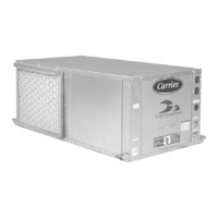
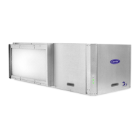
Aquazone™
50HQP,VQP 072-360
Large Capacity Water Source Heat Pumps