Do you have a question about the Carrier Bryant Evolution Extreme 186CNV and is the answer not in the manual?
Details the 16-digit model number structure for unit identification.
Explains the structure of the serial number for equipment identification.
General safety guidelines for handling HVAC equipment and electrical components.
Warnings regarding electric shock, high voltage, and sharp edges.
Hazards associated with Puron® systems and refrigerant handling.
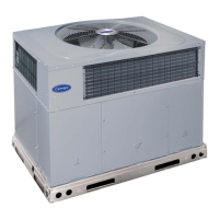
Overview of the Evolution Extreme's variable speed technology and components.
Warning to shut off power before servicing electrical components.
Recommendations for using aluminum wire in branch circuits.
Overview of the main electrical components: Terminal Block, Transformer, Sub-systems.
Wiring diagram showing VFD, PCM, and other component connections.
Table describing the function of VFD LED indicators.
Explanation of the VFD filter board and reactors in the power circuit.
How the HPS protects the compressor and system from overpressure.
Details on BPM motors and their speed control via VFD.
Explanation of the crankcase heater's role in preventing refrigerant pooling.
The PCM as the central control unit, receiving sensor signals and controlling actuators.
List of sensors, actuators managed by PCM, and its diagnostic capabilities.
Details on the 2-wire connection for communicating Evolution Control.
Wiring for non-communicating systems and DIP switch settings.
Meaning of Status, Comm, and VFD Comm indicator lights on the PCM.
Diagram showing PCM terminals for VFD, sensors, EXVs, and controls.
Location of Status LED, CCN Communication LED, and VFD LED.
Model plug's role in identifying equipment type and size to the PCM.
Description of the four thermistors used for temperature sensing.
Description of the two pressure transducers used for pressure sensing.
Details on the 6-wire connection between PCM and VFD.
Function of PEV, RVS, and EXV-H valves in system control.
Bluetooth module and accessory controls like Utility Curtailment and LLS.
PCM's use of the model plug for equipment configuration.
Selection between Efficiency and Comfort modes for optimal operation.
Details on compressor start, run, and reliability protection features.
Sump heat for reliability and fan operation, including low speed exceptions.
Operational parameters for cooling, heating, and super heat control.
Function of defrost mode to remove frost from outdoor coil.
Explanation of defrost interval and available settings (30-120 min, Auto).
How auto mode adjusts defrost interval based on previous cycle.
Step-by-step process of the defrost cycle initiation and termination.
Meaning of Status and Comm indicator lights on the PCM.
VFD communication status and diagnostic code display.
Procedures for updating PCM and VFD software.
Table detailing the meaning of each VFD LED indicator.
Diagrams showing LED locations on different VFD models.
How active diagnostics are displayed on the PCM and UI screen.
Functions of the Forced Defrost input: forcing defrost, override, recall.
Procedures for initiating defrost and overriding compressor delay.
Procedure to enter and use Diagnostic Code Recall mode.
Diagram and caution for 24VAC power distribution and connections.
Indication and behavior when communication with Evolution Control is lost.
Caution regarding incorrect model plug installation.
Table of model plug numbers and their corresponding pin resistances.
How the system responds to a high pressure switch trip.
System response to high pressure conditions and lockout.
System response to low pressure conditions and lockout.
Table of resistance values for compressor windings and fan motor.
Diagram and table for fan motor connections and measurements.
Table correlating thermistor resistance with temperature.
Location and function of the OAT thermistor.
Location and function of the OCT thermistor for defrost control.
How system operates if OCT sensor fails.
Location and function of ODT thermistor for superheat and over-temp protection.
How system operates if ODT sensor fails.
Location and function of OST thermistor for suction superheat.
How system operates if OST sensor fails.
Description of SPT and DPT, their ranges, and PCM connections.
Resistance range for EXV coils.
Wiring diagram for the 284ANV 5-wire EXV harness.
Wiring diagram for the 6-wire EXV harness used on specific models.
How the Bluetooth module collects data and connects to PCM.
Explanation of codes 13-53 and 13-82 for system control software.
Explanation of codes 14-94 (Low) and 15-94 (High) for line voltage.
Explanation of code 17-06 for communication failure.
Explanation of code 18-11 for indoor coil freeze protection.
Explanation of code 24-58 related to 5V PCM power.
Explanation of codes 25-22 and 25-62 for missing model plugs.
Explanation of code 25-24 for a changed model plug.
Explanation of code 25-61 for an invalid model plug.
Explanation of code 25-63 for VFD and model plug mismatch.
Explanation of code 26-26 for an outdated PCM.
Explanation of code 26-27 for PCM reprogramming issues.
Explanation of code 26-31 for EEPROM write failure.
Explanation of codes 28-71 and 28-72 for open fuses.
Explanation of codes 31-11 and 31-58 for high pressure.
Explanation of code 31-16 for high pressure switch trip.
Explanation of code 31-19 for high pressure disable.
Explanation of codes 32-15 and 32-55 for low suction.
Explanation of code 32-59 for low pressure lockout.
Explanation of codes 33-15 and 33-55 for low discharge.
Explanation of codes 34-11 and 34-58 for high temperature.
Explanation of codes 35-11 and 35-58 for high compression.
Explanation of codes 36-15 and 36-55 for low compression.
Explanation of codes 38-13 and 38-53 for VFD start failures.
Explanation of code 38-18 for high differential pressure start disable.
Explanation of codes 38-31 and 38-71 for VFD estimator errors.
Explanation of code 38-54 for compressor not pumping.
General information on fan motor operation and troubleshooting.
Explanation of codes 39-13 and 39-53 for fan start failures.
Explanation of code 39-14 for fan speed discrepancies.
Explanation of codes 39-15 and 39-55 for unexpected fan shutdowns.
Explanation of code 39-58 for fan motor failure.
Explanation of code 41-13 for defrost cycle timeout.
Explanation of code 44-13 for PEV timeout.
Explanation of codes 51-01 and 51-02 for OAT sensor faults.
Explanation of codes 52-01 and 52-02 for OCT sensor faults.
Explanation of codes 53-41 and 53-42 for OST sensor faults.
Explanation of codes 54-01 and 54-02 for ODT sensor faults.
Explanation of codes 57-01, 57-41, 57-02, 57-42, 57-43 for P1 sensor.
Explanation of codes 58-01, 58-41, 58-02, 58-42, 58-43 for P2 sensor.
Explanation of codes 61-13, 61-53, 61-41 for reversing valve.
Explanation of code 62-01 for PEV solenoid open fault.
Explanation of code 64-41 for EXV-H phase open.
Explanation of code 64-44 for EXV-H power short.
Explanation of code 64-45 for EXV-H phase short.
Explanation of code 65-41 for EXV-VI phase open.
Explanation of code 65-44 for EXV-VI power short.
Explanation of code 65-45 for EXV-VI phase short.
Explanation of codes 66-41 and 66-42 for VFD relay faults.
Explanation of codes 81-13 and 81-53 for PFC circuit.
Explanation of codes 81-14 and 81-54 for unbalanced PFCM.
Explanation of code 81-58 for VFD wiring error.
Explanation of code 82-11 for line current limiting.
Explanation of codes 82-13 and 82-53 for VFD reset/dropout.
Explanation of codes 82-15 and 82-55 for VFD fault/dropout.
Explanation of codes 82-16 and 82-56 for low line voltage.
Explanation of codes 82-17 and 82-57 for high line voltage.
Explanation of codes 83-11, 83-12, 83-15, 83-55, 83-16, 83-56 for current issues.
Explanation of code 83-57 for compressor lockout due to current.
Explanation of codes 84-11 and 84-58 for VFD heatsink overtemp.
Explanation of codes 85-13 and 85-53 for DC under voltage.
Explanation of codes 85-14 and 85-54 for DC over voltage.
Explanation of codes 86-06 and 86-46 for VFD communication.
Explanation of codes 87-13 and 87-53 for VFD initialization.
Explanation of codes 88-15 and 88-55 for unexpected VFD reset.
Explanation of code 88-27 for VFD reprogramming failure.
Explanation of codes 88-31 and 88-71 for VFD current sensor faults.
Explanation of code 88-32 for VFD IPM temp sensor faults.
Explanation of codes 88-33 and 88-73 for VFD DC link sensor faults.
Explanation of codes 88-34 and 88-74 for PFCM Sensor A.
Explanation of codes 88-35 and 88-75 for PFCM Sensor B.
Explanation of codes 88-36 and 88-76 for VFD line volt sensor.
Explanation of code 88-37 for VFD PFCM temp sensor.
Explanation of codes 88-38 and 88-78 for VFD DC discharge.
Explanation of codes 88-39 and 88-79 for VFD microprocessor.
Fault codes related to model plug and fuse failures.
Fault codes for high/low pressure and temperature limits.
Fault codes related to compressor starting, pumping, and compression.
Fault codes for fan start, speed, and motor errors.
Fault codes for defrost overrun and PEV timeout.
Fault codes for OAT, OCT, OST, and ODT sensor errors.
Fault codes for P1 and P2 pressure transducer issues.
Fault codes for EXV operation and VFD control relay.
Fault codes for VFD PFC and PFCM errors.
Fault codes for VFD current, voltage, and reset issues.
Fault codes for VFD internal sensor and microprocessor errors.
Visuals of the 2-ton/3-ton control box and Variable Frequency Drive.
Visuals of the 4-ton/5-ton control box and Variable Frequency Drive.
Location of VFD main power relay, reactor, and HPS connections.
Location of VFD control relay, DC terminals, and fan motor connections.
Location of the VFD to PCM communication connection.
Location of compressor, fan motor, and DC terminal connections on VFD.
Location of VFD to PCM comm, filter input, and reactor connections.
Location of VFD control relay, HPS connection, and fan motor fuse.
Top and bottom views of the PCM board showing components and connectors.
Images of Bluetooth module, fan motor, and filter input board.
Images of reactors for different tonnages, noting differences.
Image of the cable connecting PCM to Bluetooth module.
Image of the cable connecting VFD to PCM.
Diagram showing VFD and sensor connections to the PCM.
Diagram showing control and valve connections to the PCM.
Safety warnings for Puron® refrigerant and system operation.
Details on PVE compressor oil, its hygroscopic nature, and handling.
Precautions when servicing units on synthetic roofing materials.
Basic points and rules for brazing metal components.
Safety warnings for service valves and pumpdown procedures.
Steps to perform pump down using the wall control interface.
Procedures for evacuating and recovering refrigerant from the system.
How the reversing valve works and diagnostic checks.
Caution regarding filter drier damage during brazing.
Instructions for installing the liquid-line filter drier for specific models.
Instructions for installing the liquid-line filter drier for 5 Ton models.
Purpose of the suction line filter drier and its installation.
Description of TXV operation and types.
How superheat, pressure, and spring force affect TXV operation.
Role of the accumulator and procedure for its replacement.
Information about the accumulator's fusible element.
Explanation of the vapor injection circuit for increased capacity.
How the EXV-VI regulates flow for heating and efficiency.
Mounting and repair considerations for the BPHE assembly.
Methods for detecting refrigerant leaks in the system.
Using soap bubbles and electronic detectors for leak detection.
Warning about electrical shock hazards during repair.
Steps for removing and reinstalling coils for service.
Warning about fire hazard when cutting tubing.
Information on accessing online and classroom HVAC training resources.
Copyright details and catalog information for the manual.