19
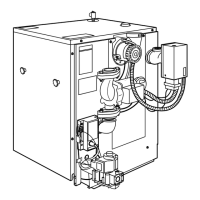
6 - COMBUSTION AIR AND VENT PIPING
Side Wall
Terminations
3" (8 cm) Minimum horizontal
separation between combustion air
intake and vent terminations.
8" (21 cm) Minimum vertical
separation between combustion air
intake and vent terminations.
12" (30 cm) Separation between
bottom of combustion air intake and
bottom of vent.
Multiple terminations as shown in
6-1, 6-2, and 6-3 must be a minimum
of 12” (30 cm) horizontally between
vent of one termination and air intake
of next appliance.
Maximum allowable total outside
exposure vent length equals 10 ft.
(3.05m).
Maintain a pitch of 1/2" per ft.
(42mm/m) outside exposure back to
boiler to ensure proper condensate
drainage for horizontal runs.
Roof
Terminations
3" (8 cm) Maximum horizontal
separation between combustion air
intake and vent of same appliance.
8" (21 cm) Minimum vertical
separation between combustion
air intake and vent of different
appliances.
15" (38 cm) Maximum horizontal
length of vent.
Maximum vent/intake between
different appliances 12" (30cm).
Maximum allowable total vertical
vent length with outside exposure is
10 ft.(3.05m).
Abandoned unused masonry
chimney may be used as chaseway
for combustion air and vent. Both
combustion air and vent pipe must
exit above top of chimney with
clearances as shown in fi gure 6-1.
Vent
3" (8 cm)
Minimum
separation
12" (30 cm)
Minimum from
overhang
12" (30 cm) Separation
between bottom of
combustion air intake
and bottom of vent
See snow & ice
page 23
Combustion Air
Vent
12" (30cm)
Minimum
separation
See snow & ice
page 23
FIGURE 6-2
FIGURE 6-3
Combustion Air
12" (30 cm)
Minimum
8" (21 cm)
Minimum
15" (38 cm)
Maximum
3" (8 cm)
Maximum
Vent Combustion
Air
12" (30 cm) Minimum above
anticipated snow line
FIGURE 6-1
Roof Line
 Loading...