6
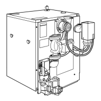
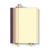
3 - COMPONENT LISTING
3.1 Component Listing
1.
User Interface (see Appendix A) - Displays
information regarding boiler condition. Allows
adjustment of boiler operating parameters. NOTE: Does
not replace thermostat used to control central heating
space.
2.
Combustion Air Inlet (2"/3") (see page 7 & 8)
3.
Return Water From Heating System (In)
Return Water From Heating System (In)
(see
page 8)
-
Connection supplied at bottom of boiler.
Connection supplied at bottom of boiler.
4.
Low Voltage Terminal Strip
Low Voltage Terminal Strip
(see page 8) -
Connection of all low voltage wiring, including
Connection of all low voltage wiring, including
thermostat. See section
8.
5.
Igniter (see page 8)
6.
Flame Sensor (see page 8)
7.
Sight Glass (see page 8) - Permits observation of
burner fl ame.
8.
Burner (see page 32)
9.
Heat Exchanger (see page 8)
10.
Condensate Collector (see page 8)
11.
Return Temperature Sensor (see page 8)
12.
Drain Valve (see page 12)
13.
Heat Exchanger Ball Valve (see page 8)
14.
Supply Water Outlet to Heating System (Out)
(see page 8) - Connections supplied for connecting
from bottom of boiler. See section 5.
15.
Vent Temperature Sensor (see page 8)
16.
Condensate Drain (see Section 6.6 page 24) - Boiler
produces a liquid (condensate) as a by-product of
combustion. Condensate must be piped to appropriate
drain.
17.
Heat Exchanger Pump (see page 8)
18.
Gas Shutoff Valve (see page 8)
- Fuel supply isolation
during servicing. See section 7.3 page 26.
during servicing. See section 7.3 page 26.
19.
Combustion Air Blower (see page 8)
- Delivers
proper quantity of combustion air, receives fuel from
proper quantity of combustion air, receives fuel from
gas valve, mixes air and fuel sending mixture to burner
gas valve, mixes air and fuel sending mixture to burner
for combustion.
20.
Gas (Control) Valve (see page 8)
- Delivers
proper quantity of fuel to Combustion Air Blower.
proper quantity of fuel to Combustion Air Blower.
See section 7.
21.
High Temperature Supply Switch
High Temperature Supply Switch (see page 8)
22.
Low Water Cutoff (see page 8)
-
Senses inadequate
quantity of water. Turns off boiler before damage can
quantity of water. Turns off boiler before damage can
occur.
23.
Safety Relief Valve (see pages 7 & 8) - Factory
supplied, Field installed. See section 5.3 page 11.
24.
High Voltage Junction Box (see page 8) - For
connection of 120V components. See section
8.
25.
Vent Connector (see pages 7 & 8) - See section 6.
26.
Gas Connection (see page 8)
See section 7.
27.
Wall Hanging Support Bracket (see page 7) -
Integral to boiler. Allows wall mounting when used
with supplied wall mounting bracket. See section 4.
28.
Air Vent (see page 7 & 8)
29.
Control Module (see page 8)
30.
Transformer (see page 8) - Supplies 24V power to low
water cutoff.
31.
Pressure Test Port - (see page 8)
32.
Combustion Analysis Test Port - (see page 8)
33.
Return Water Sensor - (see page 8)
34.
User Interface - (see page 8)
 Loading...