5
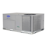
Fig. 7 — Mount Controller Assembly in Unit
Control Box
(Some control box configurations may differ)
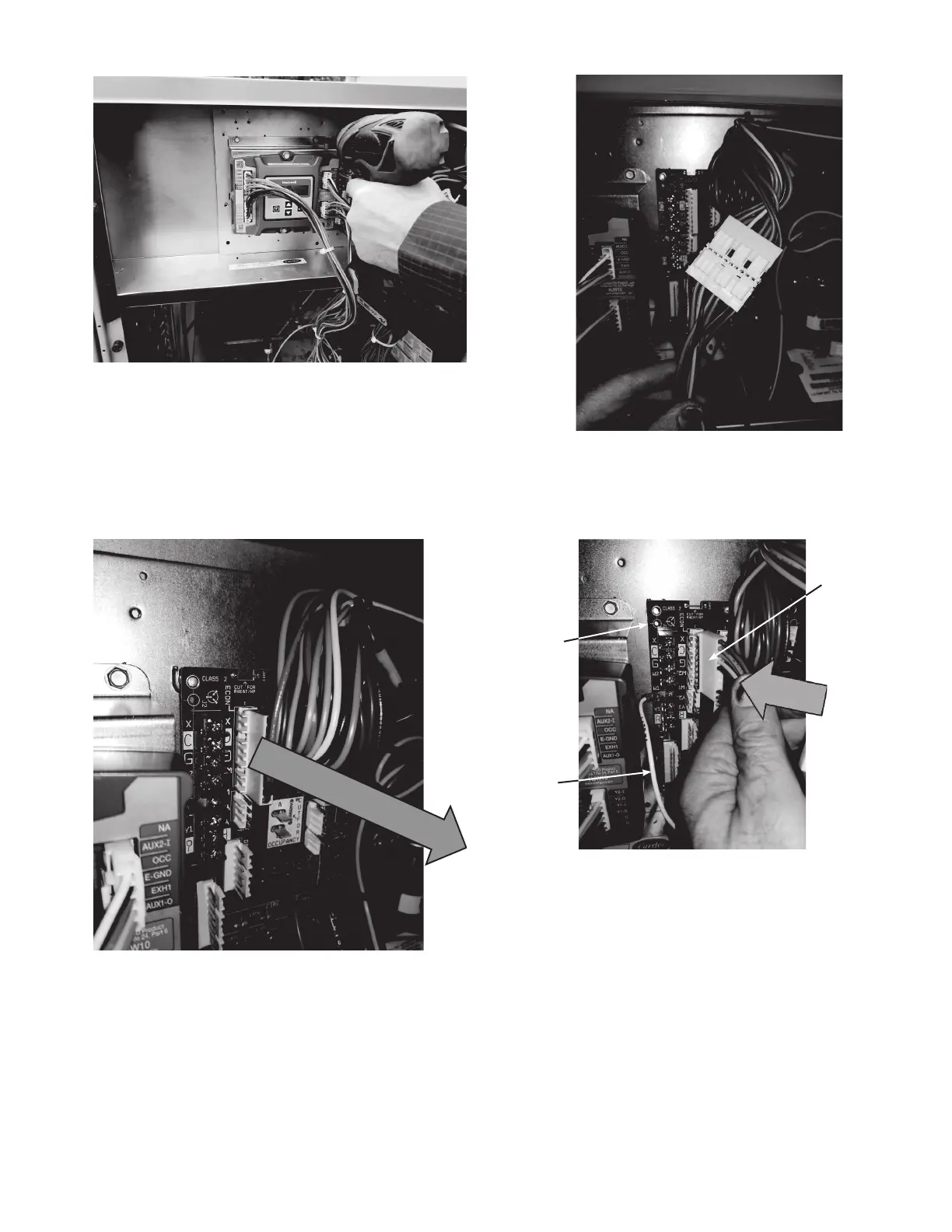
11. Unplug the 10-pin female ECON plug currently con-
nected to the Central Terminal Board (CTB). See
Fig. 8.
Fig. 8 — Unplug ECON plug from Central Terminal
Board (CTB)
12. Connect the 10-pin female ECON plug removed from
the CTB to the 10-pin male plug from the Jade control-
ler harness. See Fig. 9 and page 9.
Fig. 9 — Connect 10-pin Plugs Together
13. Connect the 10-pin female plug from the Jade controller
harness to ECON on the CTB. See Fig. 10 and page 9.
Fig. 10 — Connect 10-Pin Jade Plug to Central
Terminal Board
14. Connect the White wire from the Jade controller harness
to the W1 terminal on the CTB. See Fig. 10 and page 9.
15. Connect the red and brown wires from the Jade control-
ler harness to the CTB. See Fig. 11 and page 9. The red
wire connects to “R” on the CTB, and the brown wire
connects to “C”.
CENTRAL
TERMINAL
BOARD
WHITE
WIRE
10-PIN
FEMALE
PLUG FROM
CONTROLLER
 Loading...


