4
ECONOMIZER INSTALLATION
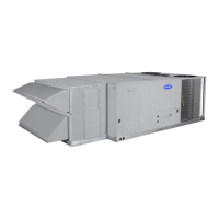
Figure 1 shows component locations on the EconomizerONE
system.
Fig. 1 — EconomizerONE Component Locations
(CRECOMZR108A00 Shown)
1. Turn off unit power supply and install lockout tag.
2. Remove the existing unit filter access panel. Raise the panel
and swing the bottom outward. The panel is now disengaged
from the track and can be removed. (See Fig. 2.)
3. Remove the indoor coil access panel. (See Fig. 2.)
NOTE: Save the filter access and indoor coil access panels
for future use in the event that the EconomizerONE assembly
is ever removed.
4. For vertical installations — Slide the EconomizerONE
assembly into the unit as shown in Fig. 3. Be sure to engage
the rear EconomizerONE flange under the tabs on the unit
base in the Return Air opening as shown in Fig. 4. Continue
at Step 8.
5. For horizontal installations — Locate Mixed Air Temperature
Switch (MTS) with its bracket on left side of the unit.
Remove left filter to access MTS bracket screws. Remove
screws and relocate the bracket with MTS on the next set of
holes up, having the bracket now above the opening of the fil-
ter access opening.
See Fig. 5 for the following 6 and 7.5 ton units:
- 48/50FC 08, 50FCQ 08, 48/50GC 07, 50GCQ 07
- 582K/559K 08, 547K 08, 581K/551K 07, 549K 07
- RAV/RGV 090, RHV 090, RAW/RGW 072, RHW 072
See Fig. 6 for the following 7.5 to 12.5 ton units:
- 48/50FC 09-14, 50FCQ 09-12, 48/50GC 08-12,
50GCQ 08-09
- 582K/559K 09-14, 547K 09-12, 581K/551K 08-12,
549K 08-09
- RAV/RGV 102-150, RHV 102-120, RAW/RGW 090-120,
RHW 090-102
6. Slide the EconomizerONE assembly all the way back and
into the horizontal R/A (Return Air) opening. (See Fig. 7.)
7. Attach O/A (Outside Air) panel, included in O/A hood kit,
over the panel opening, then lift the economizer. Match the
ID (inside dimension) of the panel with the ID of the econo-
mizer, then attach using provided screws. (See Fig. 8.)
8. If the EconomizerONE system will be operating with an
enthalpy outside air sensor, then remove the factory installed
HH79NZ039 dry bulb sensor from the front face of the econ-
omizer (see Fig. 1), and install the accessory enthalpy sensor
HH57LW001 in the same location. Connect the (5) wire har-
ness with plug from the EconomizerONE assembly to the
enthalpy sensor. See page 9 for wiring diagram. Refer to
“INSTALLING OPTIONAL HH57LW001 SINGLE OUT-
SIDE AIR ENTHALPY SENSOR” on page 10 section for
more details on enthalpy settings.
9. Remove and save the 12-pin jumper plug from the unit econ-
omizer harness located in the upper left corner of the unit.
Insert the EconomizerONE plug into the unit wiring harness.
(See Fig. 9.)
NOTE: The 12-pin jumper plug should be saved for future
use, in the event that the EconomizerONE assembly is ever
removed. The jumper plug is not needed as long as the Econ
-
omizerONE is installed.
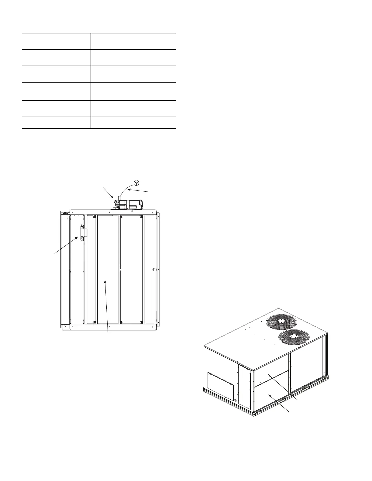
Fig. 2 — Filter Access View
10. For vertical installations — Install the outside air hood over
the economizer in place through pre-punched holes. Reinstall
the unit’s filter access panel. Continue at Step 16.
For horizontal hood installation see Steps 11-15.
Table 5 — EconomizerONE Sensor Usage
a
a. Dry Bub sensor HH79NZ039 is included in the kit. Dry Bulb sensor
HH57LW001 can be used as a replacement part.
APPLICATION
EconomizerONE WITH OUTDOOR
AIR DRY BULB SENSOR
(ACCESSORIES REQUIRED)
Outdoor Air Dry Bulb
The HH79NZ039 outdoor air dry bulb
sensor is factory installed on the
economizer.
Mixed Air Sensor
HH79NZ039 provided with
economizer and field-installed in
blower compartment.
Single Enthalpy Sensor HH57LW001
Differential Dry Bulb Or
Enthalpy
HH57LW001 (Qty. 2 required)
CO
2
for DVC Control using a
Wall-Mounted CO
2
Sensor
33ZCSPTCO2LCD-01 or
33ZCSPTCO2-01 or
CRCBDIOX005A003
CO
2
for DVC Control using a
Duct-Mounted CO
2
Sensor
33ZCSPTCO2LCD-01 or
33ZCSPTCO2-01
Actuator
HH79NZ039
Outside Air
Temperature
Sensor
Outside Air
Damper
Wiring
Harness
Filter Access Panel
Indoor Coil Access Panel
 Loading...