EasyManua.ls Logo

Carrier Ecologic 30GX080-265 User Manual

Carrier Ecologic 30GX080-265
100 pages
To Next Page IconTo Next Page
Page #1 background imageLoading...
Page #1 background image
Controls, Start-Up, Operation,
Service, and Troubleshooting
SAFETY CONSIDERATIONS
Installing, starting up, and servicing this equipment can
be hazardous due to system pressures, electrical compo-
nents, and equipment location (roof, elevated structures, etc.).
Only trained, qualified installers and service mechanics should
install, start up, and service this equipment.
When working on this equipment, observe precautions in
the literature, and on tags, stickers, and labels attached to the
equipment, and any other safety precautions that apply. Fol-
low all safety codes. Wear safety glasses and work gloves.
Use care in handling, rigging, and setting this equipment,
and in handling all electrical components.
Electrical shock can cause personal injury and death.
Shut off all power to this equipment during installation
and service. There may be more than one disconnect
switch. Tag all disconnect locations to alert others not
to restore power until work is completed.
This unit uses a microprocessor-based electronic con-
trol system. Do not use jumpers or other tools to short
out components, or to bypass or otherwise depart from
recommended procedures. Any short-to-ground of the
control board or accompanying wiring may destroy the
electronic modules or electrical components.
To prevent potential damage to heat exchanger tubes al-
ways run fluid through heat exchangers when adding or
removing refrigerant charge.
DO NOT VENT refrigerant relief valves within a build-
ing. Outlet from relief valves must be vented outdoors
in accordance with the latest edition of ANSI/ASHRAE
(American National Standards Institute/American Soci-
ety of Heating, Refrigeration and Air Conditioning En-
gineers) 15 (Safety Code for Mechanical Refrigeration).
The accumulation of refrigerant in an enclosed space
can displace oxygen and cause asphyxiation. Provide ad-
equate ventilation in enclosed or low overhead areas.
Inhalation of high concentrations of vapor is harmful
and may cause heart irregularities, unconsciousness or
death. Misuse can be fatal. Vapor is heavier than air and
reduces the amount of oxygen available for breathing.
Product causes eye and skin irritation. Decomposition
products are hazardous.
DO NOT attempt to unbraze factory joints when ser-
vicing this equipment. Compressor oil is flammable and
there is no way to detect how much oil may be in any
of the refrigerant lines. Cut lines with a tubing cutter as
required when performing service. Use a pan to catch
any oil that may come out of the lines and as a gage for
how much oil to add to system. DO NOT re-use com-
pressor oil.
CONTENTS
Page
SAFETY CONSIDERATIONS ...................1
GENERAL ...................................2
MAJOR SYSTEM COMPONENTS ..............3
Processor Module (PSIO-1) ...................3
DSIO-HV Relay Module .......................3
Electronic Expansion Device Module .........3
Compressor Protection Module (CPM) .........3
PSIO-2 (8052) Module ........................3
Keypad and Display Module
(Also Called HSIO-II) .......................3
Control (LOR) Switch .........................3
OPERATION DATA ..........................3-42
Electronic Expansion Device (EXD) ...........3
EXV OPERATION
ECONOMIZER OPERATION
Oil Pumps ...................................4
Motor Cooling ...............................4
Back Pressure Valve (30GX and 30HXA only) ..4
Sensors .....................................4
Compressor Protection Module (CPM) .........4
OUTPUTS
INPUTS
Wye-Delta vs Across-the-Line (XL)
Starting Option ............................5
Capacity Control .............................6
MINUTES LEFT FOR START
MINUTES OFF TIME
LOADING SEQUENCE
CLOSE CONTROL
LEAD/LAG DETERMINATION
CAPACITY SEQUENCE DETERMINATION
MINIMUM LOAD VALVE
CAPACITY CONTROL OVERRIDES
Head Pressure Control .......................8
GENERAL
AIR COOLED UNITS (30GX)
WATER COOLED UNITS (30HX)
ADJUSTING PID ROUTINES
Cooler and Condenser (30HXC)
Pump Control .............................10
30GX080-265
30HXA,HXC076-271
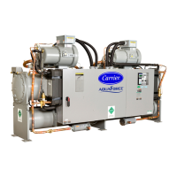
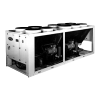
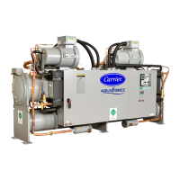
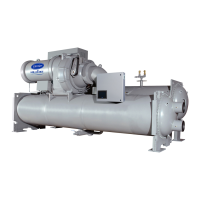
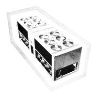
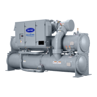
ECOLOGIC™ Air-Cooled and Fluid Cooled Chillers
50/60Hz
Manufacturer reserves the right to discontinue, or change at any time, specifications or designs without notice and without incurring obligations.
Book 2
Tab 5c
PC 903 Catalog No. 533-062 Printed in U.S.A. Form 30G,H-3T Pg 1 1-98 Replaces: 30G,H-2T
Series 0,1,2

Table of Contents

Question and Answer IconNeed help?

Do you have a question about the Carrier Ecologic 30GX080-265 and is the answer not in the manual?

Carrier Ecologic 30GX080-265 Specifications

General IconGeneral
BrandCarrier
ModelEcologic 30GX080-265
CategoryChiller
LanguageEnglish

Summary

SAFETY CONSIDERATIONS

Electrical Hazards

Warning about electrical shock and the need to shut off all power.

Control System Precautions

Caution against bypassing electronic control components to prevent damage.

Refrigerant Handling Safety

Safety instructions for venting refrigerant relief valves and general handling.

Safety Devices

Compressor Safety Features

Lists safety devices for compressor protection and their functions.

Cooler Safety Features

Lists safety devices related to cooler protection.

GENERAL UNIT INFORMATION

Refrigerant and Oil Specifications

Specifies refrigerant type (R-134a) and compressor oil used.

Control System Overview

Describes the microprocessor-based control system and its components.

MAJOR SYSTEM COMPONENTS

Core Control Modules

Details PSIO-1, DSIO-HV, EXD Module, CPM, PSIO-2, and HSIO-II modules.

Unit Control Interface

Explains the LOCAL/OFF/REMOTE switch for controlling unit operation modes.

OPERATION DATA

Electronic Expansion Device (EXD) Operation

Explains how the EXD controls refrigerant flow and cooler level.

Component Operations

Economizer Operation

How the economizer improves capacity and efficiency, and provides motor cooling.

Oil Pump and Motor Cooling

Details oil pump operation and motor cooling control logic.

Back Pressure Valve and Sensors

Function of the back pressure valve and the role of system sensors.

Compressor Protection Module (CPM)

Explains CPM functions, inputs, and outputs for compressor protection.

Compressor Protection Module (CPM)

CPM Status Indicators and Alarms

Explains CPM LEDs and lists alarm conditions with feedback codes.

Compressor Starting Options

Details the Wye-Delta vs. Across-the-Line starting options for compressors.

Capacity Control Logic

Capacity Control Routine

How the control system manages capacity stages to meet the set point.

Start-Up and Operation Delays

Explains "Minutes Left for Start" and "Minutes Off Time" parameters.

Loading Sequence

Describes the sequence for compressor and loader engagement for efficiency.

Capacity Control Sequences

Close Control Logic

How close control uses loading devices for precise temperature regulation.

Lead/Lag and Capacity Sequence Determination

Logic for determining lead/lag circuits and capacity stage order.

Minimum Load Valve and Overrides

Operation of the minimum load valve and capacity control overrides.

Control Logic Overrides

Temperature and Superheat Control

How overrides like slow change, ramp loading, and low superheat affect operation.

Head Pressure Control Logic

Control Adjustments and Pump Control

Unit Interface and Control

Keypad and Display Module (HSIO-II)

Description of the HSIO-II module for unit interaction and configuration.

Status Function Operations

System Monitoring Displays

Unit Testing and Configuration

Set Point Configuration

How to enter and adjust various unit set points.

SERVICE FUNCTION

Scheduling and Set Point Control

Temperature Reset and Demand Limit

Demand Limit Functionality

How demand limit reduces unit capacity during peak energy usage.

TROUBLESHOOTING GUIDANCE

Unit Stoppage and Restart Procedures

Lists causes of unit stoppages and procedures for restarting.

EXD Troubleshooting

Component Inspection Procedures

Service Procedures

Heat Exchanger Maintenance

Refrigerant Management

Low Refrigerant Charge Detection

Methods for identifying low refrigerant charge in 30HXC and 30HXA/GX systems.

Refrigerant and Oil Management

Oil Charging and Low Oil Alarms

Procedure for adding oil and addressing low oil level alarms.

Oil Filter Maintenance and Compressor Replacement

Compressor Changeout Sequence

Detailed steps for replacing a compressor, including wiring and handling.

System Monitoring and Troubleshooting

Thermistor Checks and Replacement

How to check thermistor performance and replace faulty units.

Pressure Transducer Calibration

How to calibrate pressure transducers using the HSIO software.

Pressure Transducer Calibration and Troubleshooting

Safety Devices and Protection

Control Module Operations

Compressor Control Troubleshooting

Pre-Start-Up and Start-Up Procedures

Start-Up and Operating Sequence

How to perform the actual start-up and understand the operating sequence.

FIELD WIRING DIAGRAMS

APPENDIX A - Compressor Must Trip Amps

APPENDIX B - Capacity Loading Sequence

APPENDIX C - Available Accessories

APPENDIX D - Compressor Protection Module Configuration

APPENDIX E - Pressure Drop Charts

APPENDIX E - Pressure Drop Charts (cont)

APPENDIX F - System Component Diagrams

APPENDIX F - System Component Diagrams (cont)

START-UP CHECKLIST

Preliminary Equipment Checks

Unit Start-Up Procedures

System Loop Pressure Drop Checks

PERFORM TEST FUNCTION

Configuration and Start-Up Data Recording

Final Start-Up Steps

Performing final valve/pump checks, starting the unit, and recording temperatures/pressures.

Related product manuals