F55: Installation Instructions
Manufacturer reserves the right to change, at any time, specifications and designs without notice and without obligations.
11
Leak Dissipation System
The 18-60 size units come equipped with a factory wired R-454B leak
detection and dissipation system to ensure safe operation during a leak.
The system consists of a bracket, a PCB, a A2L Detection Sensor, and a
drain pan clip. Failure to install this system will result in potentially
hazardous conditions and improper equipment operation, and void all
system warranties and liabilities.
All units are shipped with the A2L Detection Sensor located in the
upflow position. For sizes 18-24, the sensor will always be installed on
the drain pan clip.
A230490
Fig. 18 – Dissipation Sensor Mounted on Drain Clip
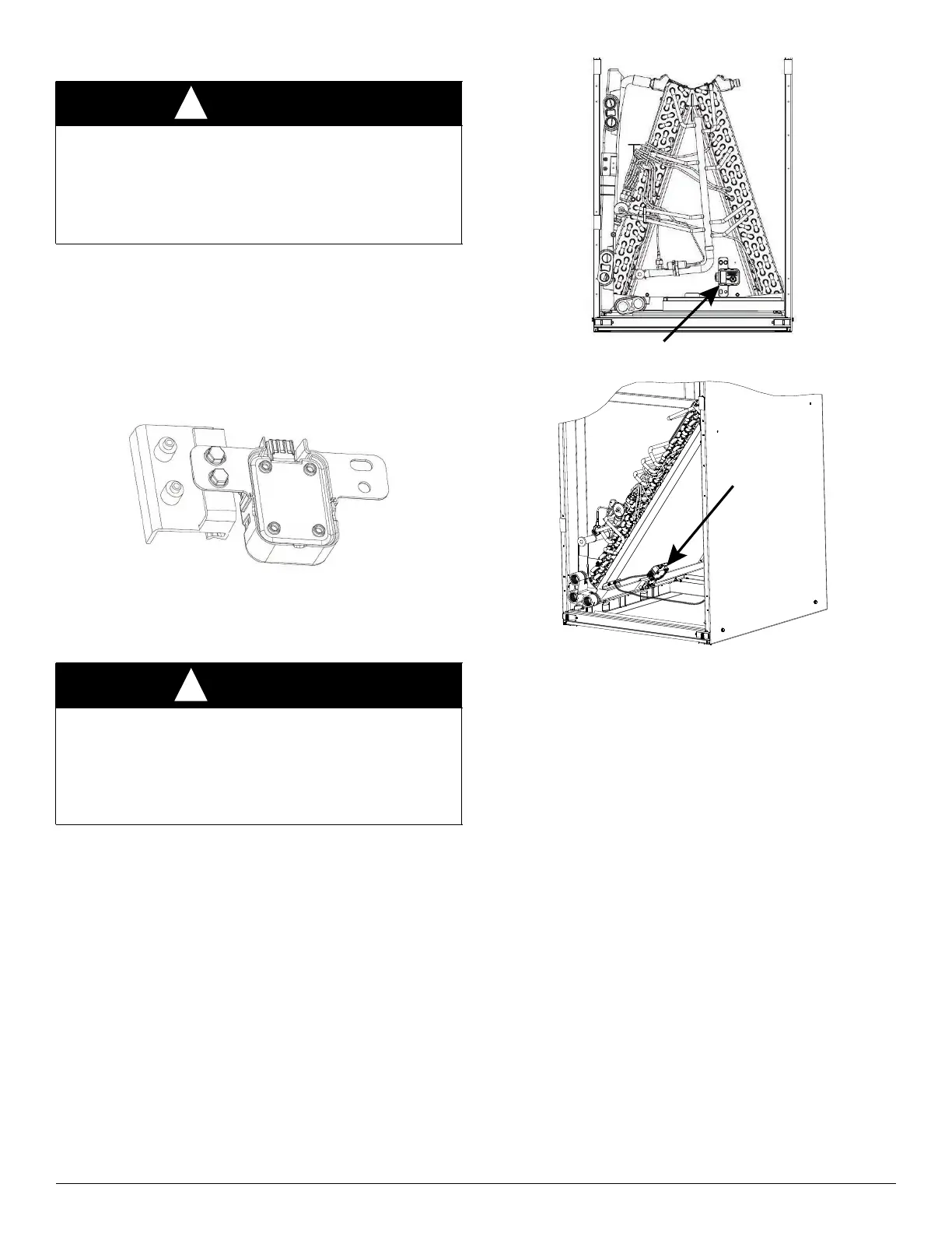
For sizes 30-60, the sensor comes factory installed on the delta plate
(Fig. 19, Fig. 20). For horizontal right and left, the sensor will need to be
moved to the drain pan clip (Fig. 18, Fig. 5, Fig. 6, Fig. 7).
IMPORTANT: Sensor must be installed with the connector facing
down or facing horizontally. Sensor should never be positioned with
connector facing upward. Incorrect sensor position could result in
premature failure.
A230501
Fig. 19 – A-Coil Vertical Dissipation Sensor Factory Location
A230502
Fig. 20 – Slope Coil Vertical Dissipation Sensor Factory Location
The A2L Detection Sensor is attached to a wiring harness that connects
the sensor to the dissipation board. In upflow, the routing of the wire
harness is up the right side of the unit behind the wire retainers for the
cabinet insulation. At each wire retainers, the harness is attached using
two wire ties. When converting unit to horizontal or downflow, follow
routing shown in Fig. 5, Fig. 6, or Fig. 7. When converting the unit to
any orientation, ensure the sensor wiring harness is disconnected and the
wire harness has been placed in the control box before any components
are moved.
Refer to Fig. 10 through Fig. 13 for low voltage field connections
between the dissipation board and the thermostat. All control wires are
labeled with the wire function and landing point.
Leak Dissipation System Self-Test
Power on the unit and verify proper functioning of equipment. The
yellow LED on the dissipation board should be steady. If flash codes are
present, see (Troubleshooting on p12).
NOTE: Operation of the Test Mode is only possible if no faults exist on
the dissipation board.
IMPORTANT: Press the Test button for roughly ONE SECOND to
enter Test Mode. Pressing the Test button for a longer periods enables
different functions (Table 2).
Press the Test button on the dissipation system control board to ensure
proper dissipation system operation under each test condition listed
below. After pressing the Test button, system will enter Dissipation
Mode for 60 seconds to help verify correct operation.
WARNING
!
PERSONAL INJURY OR PROPERTY DAMAGE
HAZARD
Failure to follow proper R-454B mitigation system installation
instructions can result in property damage, personal injury, or death.
If any fault codes are listed, please troubleshoot to prevent system
malfunction.
WARNING
!
PRODUCT OPERATION / INJURY HAZARD
Failure to follow this warning could cause product damage or personal
injury.
Make sure the sensor is not exposed to significant amounts of dust/dirt
contamination. This could clog the sensor and prevent proper
functioning. For sensor cleaning instructions, refer to service manual.