F55: Installation Instructions
Manufacturer reserves the right to change, at any time, specifications and designs without notice and without obligations.
12
Ensure that the fan coil is able to meet the minimum required dissipation
mode airflows. These required minimum airflow rates during
Dissipation Mode are listed in Table 4. They are based on the total
system refrigerant charge quantity.
Troubleshooting
For all flash codes, first try power cycling the system to remove the
code.
No power
Verify the wiring to/from pins 1 and 8 on the power harness plug. Check
the 24V system wiring from the transformer.
Flashing 1
Check for refrigerant leaks using an independent R-454B detector. If no
leaks are present, replace the sensor.
Flashing 2
Check both ends of the sensor wire harness to ensure proper attachment.
Power cycle the system to check whether the flash code has been
removed. If the flash code is still present, replace the sensor.
Flashing 3
Check for refrigerant leaks using an independent R-454B detector.
Flashing 4
If the code does not clear after power cycling the system, replace the
dissipation board.
Flashing 5
If the code does not clear after power cycling the system, replace the
sensor.
Flashing 6
Press the test button repeatedly. Power cycle the system. If the button
cannot be reset, replace the dissipation board.
Flashing 7
Verify wiring of all "Y" and "W" wires in the applicable wiring diagram.
Flashing 8
Verify wiring of all "Y" and "W" wires in the applicable wiring diagram.
Accessories
Humidifier
Connect the humidifier and humidistat to the fan coil unit as shown in
Fig. 22 and Fig. 25. The cooling lockout relay is optional.
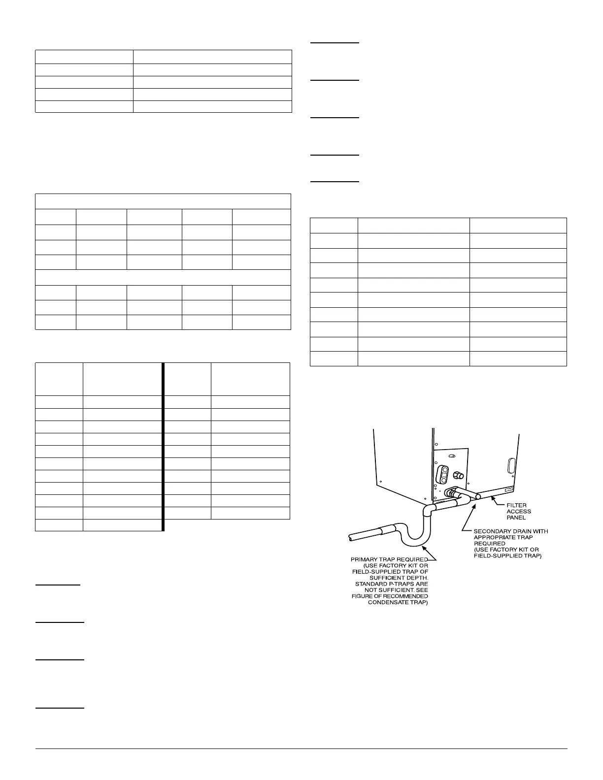
A03003
Fig. 21 – Condensate Drain
Sequence of Operation
Continuous Fan
Thermostat closes the R to G connection. G passes through the
dissipation board and energizes the fan relay on the PCB which
completes the circuit to the indoor blower motor. When G is
de-energized, there is a 90-second delay before the relay opens.
Table 2 – Dissipation Board Test Button Functions
Hold Button Time (sec) Function
1 - 4 Dissipation Mode for 60 seconds
5 - 29 Display flash code history
30+ Flash code 6
3 rapid presses Clear flash code history
Table 3 – Required Operational Checks to Ensure Proper
Dissipation System Function
Normal Operation
Test # T-Stat Call Compressor Indoor Fan Heat
1 None Off Off Off
2 Cool On On Off
3 Heat Off On On
Dissipation Activated
4 None Off On Off
5 Cool Off On Off
6 Heat Off On Off
Table 4 – Required Minimum Dissipation Mode Airflows,
based on Total System Refrigerant Charge Quantity
Total
System
Charge (lb)
Minimum Required
Dissipation Airflow
(CFM)
Total
System
Charge (lb)
Minimum Required
Dissipation Airflow
(CFM)
5 133 16 426
6 160 17 452
7 186 18 479
8 213 19 505
9 239 20 532
10 266 21 559
11 293 22 585
12 319 23 612
13 346 24 639
14 372 25 665
15 399
Table 5 – Flash Code Chart
Yellow LED Reason Mode
Solid Normal Operation Normal Operation
Flashing 1 Sensor >= 20% LFL Dissipation
Flashing 2 Sensor Open Dissipation
Flashing 3 Normal Mitigation after Leak Dissipation
Flashing 4 No Power to G Output Dissipation with no Blower
Flashing 5 Fault with A2L Digital Sensor Dissipation
Flashing 6 Test Button Stuck (>30 s) Dissipation
Flashing 7 Y or W Wiring Inverted Normal Operation
Flashing 8 Y or W Shorted Normal Operation