F55: Installation Instructions
Manufacturer reserves the right to change, at any time, specifications and designs without notice and without obligations.
4
A07566
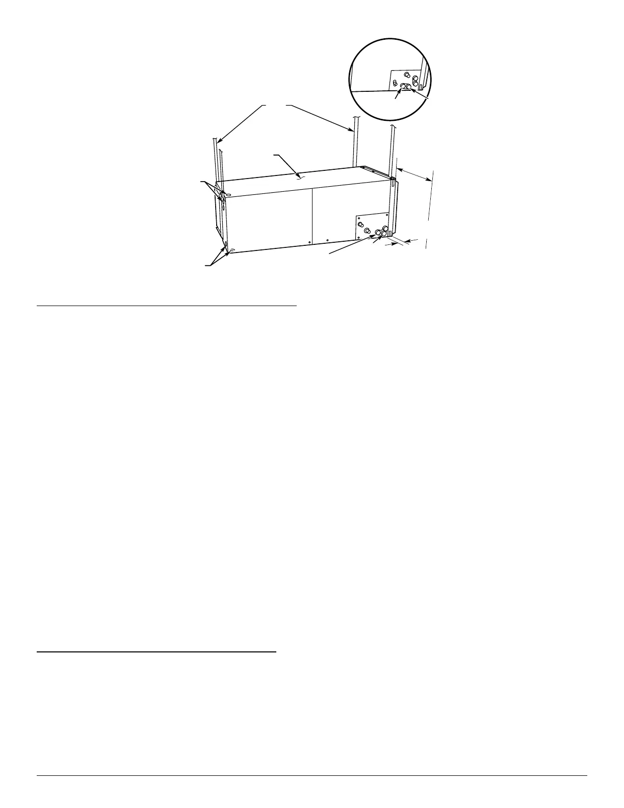
Fig. 4 – Slope Coil in Horizontal Left Application (Factory Configuration)
Horizontal Right Conversion of Units with Slope Coils
NOTE: A gasket kit is required for horizontal slope coil conversion to
maintain low air leak/low sweat performance. See the Product Data or
contact your supplier for the kit number.
1. Remove blower and coil access panels and fitting panel (Fig. 7).
2. Disconnect sensor on drain pan and cut wire tie securing sensor
harness to the coil.
3. Undo sensor wire routing and place entire harness in the control
box.
4. Remove coil mounting screw securing coil assembly to right side
casing flange.
5. Remove coil assembly.
6. Lay fan coil on its right side and reinstall coil assembly with
condensate pan down (Fig. 6).
7. Attach coil to casing flange using previously removed coil
mounting screw.
8. Reconnect sensor wire harness by following routing shown (Fig. 6).
IMPORTANT: Sensor must be installed with the connector facing
down or facing horizontally. Sensor should never be positioned with
connector facing upward. Incorrect sensor position could result in
premature failure.
9. Make sure pan cap in fitting door is properly seated on fitting door
to retain low air leak rating of the unit.
10. Add gaskets from kit.
11. Align holes with tubing connections and condensate pan
connections. Reinstall access panels and fitting panel.
12. Make sure liquid and suction tube grommets are in place to prevent
air leaks and cabinet sweating. Install grommets after brazing.
Horizontal Right Conversion of Units with A-Coils
1. Remove blower and coil access panels (Fig. 7).
2. Disconnect and remove sensor on delta plate and install on
horizontal drain pan clip (Fig. 18).
IMPORTANT: Sensor must be installed with the connector facing
down or facing horizontally. Sensor should never be positioned with
connector facing upward. Incorrect sensor position could result in
premature failure.
3. Undo sensor wire harness routing and place entire harness in the
control box.
4. Remove metal clip securing fitting panel to condensate pan.
Remove fitting panel.
5. Remove 2 snap-in clips securing A-coil in unit.
6. Slide coil and pan assembly out of unit.
7. Remove horizontal drain pan support bracket from coil support rail
on left side of unit and reinstall on coil support rail on right side of
unit (Fig. 8).
8. Convert air seal assembly for horizontal right.
a. Remove air seal assembly from coil by removing 4 screws
(Fig. 7).
b. Remove air splitter (B) from coil seal assembly by removing 3
screws (Fig. 7 inset).
c. Remove filler plate (A) and install air splitter (B) in place of filler
plate.
d. Install filler plate (A) as shown in horizontal right application.
e. Remove condensate troughs (C) and install on opposite tube
sheets.
f. Install hose onto plastic spout.
9. Install horizontal pan on right side of coil assembly.
10. Slide coil assembly into casing. Be sure coil bracket on each corner
of vertical pan engages coil support rails.
11. Reinstall 2 snap-in clips to correctly position and secure coil
assembly in unit. Be sure clip with large offsets is used on right side
of unit to secure horizontal pan.
12. Remove two oval fitting caps from left side of the coil, access
panel, and fitting panel.
13. Remove insulation knockouts on right side of coil access panel.
14. Remove 2 oval coil access panel plugs and reinstall into holes on
left side of coil access panel and fitting panel.
15. Install condensate pan fitting caps (from Step 12) in right side of
coil door making sure that cap snaps and seats cleanly on back side
of the coil door. Make sure no insulation interferes with seating of
cap.
16. Reinstall access and fitting panels, aligning holes with tubing
connections and condensate pan connections. Be sure to reinstall
metal clip between fitting panel and vertical condensate pan.
17. Make sure liquid and suction tube grommets are in place to prevent
air leaks and cabinet sweating.
UNIT
FIELD
SUPPLIED
HANGING
STRAPS
LOW VOLT
ENTRY
OPTIONS
POWER
ENTRY OPTIONS
SECONDARY
DRAIN
018-048 21" (533 mm)
060-060 24" (610 mm)
FRONT SERVICE
CLEARANCE
(FULL FACE
OF UNIT)
SECONDARY
DRAIN
A-COIL
HORIZONTAL LEFT
PRIMARY
DRAIN
PRIMARY
DRAIN
1.75" (44 mm)
FILTER ACCESS
CLEARANCE