FB, FE, FF1E, FFM, FG, FH, FJ, FMA, FT, FV, FX, FY, FZ, F54, PF: Service and Maintenance Instructions
Manufacturer reserves the right to change, at any time, specifications and designs without notice and without obligations.
25
present but no output, replace PCB. If output is present, replace
relay.
Heater Will Not Turn Off
1. Check low-voltage wiring for miswire.
2. Check for shorted elements to ground.
3. Replace sequencer/relays. They may be stuck closed.
Nuisance Trips
1. Check for low airflow due to dirty filters, blocked registers, or
undersized duct.
2. Check blower motor and wheel for proper operation. Excessive
current draw of motor will cause internal overload to trip.
3. The fan speed may be low.
FFM, FMA
This section describes EHK2 series electric heaters by examining
functional operation of this heater.
Service can be completed with heater in place. Shut off power before
servicing.
Description of Electric Heater Components
Limit Switch
The limit switch is a temperature sensitive control that’s function is to
prevent system from overheating in abnormal conditions. The
temperature settings often vary from heater to heater due to variations in
airflow patterns and element radiant heat conditions.
The devices are sized to remain on-line under heat pump conditions
(115° F air off coil) and minimum CFM, but trip to prevent outlet air
conditions above 200° F or excessive component or duct temperatures.
The device itself consists of a bimetallic disc, which when overheated
“snaps through” to open a normally closed high-voltage, high-current
switch. When system temperatures cool sufficiently, the switch will
automatically reset to its closed position. Normal failure mode for this
switch is open.
If a limit switch has been determined to be defective, NEVER BYPASS
THE LIMIT SWITCH. When replacing limit switch, ensure that it is
replaced with a limit switch of identical opening temperature and closing
differential. Limits switches are typically color-coded to identify their
range.
Sequencer
Early production EHK2 heaters have sequences controlling the heater
elements. The sequencer is essentially a thermally-activated time-delay
relay normally activated by low-voltage control signals from thermostat.
The typical sequencer is a 1- or 2-pole normally open device which
energizes within 30 to 70 seconds after application of control signal and
de-energizes 60 to 90 seconds after control signal is removed.
In simplistic terms, the sequencers which we use are nothing more than
normally open limit switches which sit on top of a small resistive heater.
When voltage is applied to this heater, a positive temperature coefficient
resistor (PTC), heat is supplied to a bimetallic disc which “snaps
through” and closes switch.
The time required for PTC to heat to a sufficient point controls ON
timing of device. The time required for disc to cool down when power is
removed controls OFF time of device. The PTC can be varied to provide
varied timing. Typically a short ON equates to a long OFF.
Because this is a thermally-activated device, ambient conditions affect
the ON/OFF cycle. Higher ambient temperature means shorter ON times
and longer OFF times.
Application of these devices is such that the first switch ON not only
turns on first heater element, but also ensures that indoor fan is
energized, because first ON is last OFF. This ensures fan remains ON
until the last heater de-energizes. The Time Delay Printed Circuit Board
(PCB) is a logic controlled time delay activated by low-voltage control
signal (G) from thermostat. The PCB includes a normally open relay
which closes to energize the blower motor when the G terminal is
energized. Then when the G terminal is de-energized the relay
energizing the blower motor remains closed for 90 – 100 seconds before
opening.
Relays
Later production EHK2 heaters have relays controlling the heater
elements instead of sequencers. A small rectifier PCB is mounted to
each relay which converts the incoming 24VAC control signal to DC.
In addition to the rectifier circuit, the second and third stage relays
contain a time-on delay circuit of five seconds for second stage, and
eight seconds for third stage. When the control signal is removed from
the relays, all relays will open with no time-off delay.
Leak Dissipation System
Operation (Models with R-454B Refrigerant)
When no leak is detected, G, Y, and W pass through the dissipation board
and operate normally. In this state, the Dissipation Board Status LED
remains solid yellow. When the A2L Detection Sensor reaches a
threshold of detected R-454B refrigerant, the Status LED flashes one
time and the dissipation board enters dissipation mode. While the
detected refrigerant is over the threshold, the Status LED will continue to
flash a Fault Code of 1. After the level is lower than the threshold, the
Status LED flashes a code of 3 as the dissipation board completes its
dissipation actions. These actions include de-energizing Y and W and
energizing G for 15 minutes. After the 15 minutes if the refrigerant
detected is below the threshold, there is a 5 minute delay before
returning to normal operation. If the refrigerant detected is above the
threshold, G continues to be energized until refrigerant is below the
threshold. At that point the 5-minute delay begins.
After dissipation is complete, the unit returns to normal operation with
the Status LED being solid.
System Self-Test
Power on the unit and verify proper functioning of equipment. The
yellow LED on the dissipation board should be steady. If flash codes are
present, see (Troubleshooting on p26).
NOTE: Operation of the Test Mode is only possible if no faults exist on
the dissipation board.
IMPORTANT: Press the Test button for roughly ONE SECOND to
enter Test Mode. Pressing the Test button for a longer periods enables
different functions (Table 13).
Press the Test button on the dissipation system control board to ensure
proper dissipation system operation under each test condition listed
below. After pressing the Test button, system will enter Dissipation
Mode for 60 seconds to help verify correct operation.
Ensure that the fan coil is able to meet the minimum required dissipation
mode airflows. These required minimum airflow rates during
Dissipation Mode are listed in Table 15. They are based on the total
system refrigerant charge quantity.
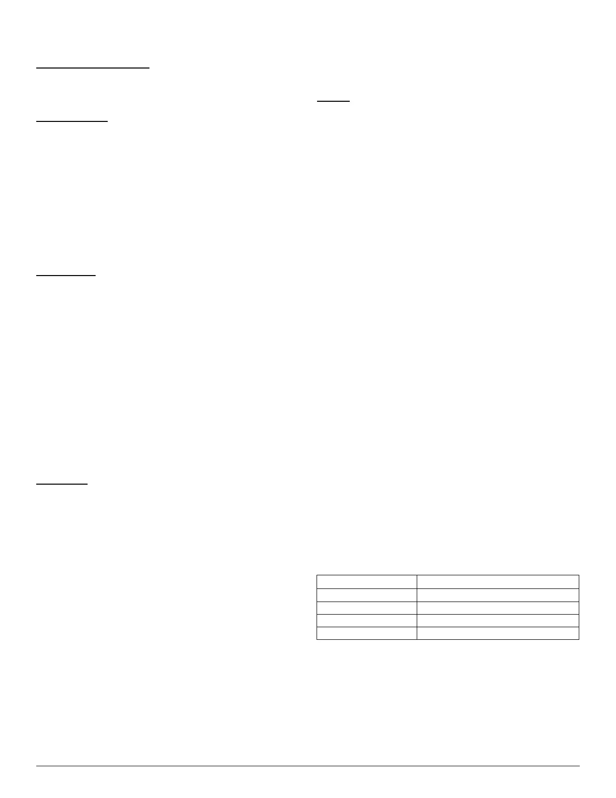
Table 13 – Dissipation Board Test Button Functions
Hold Button Time (sec) Function
1 - 4 Dissipation Mode for 60 seconds
5 - 29 Display flash code history
30+ Flash code 6
3 rapid presses Clear flash code history