FB, FE, FF1E, FFM, FG, FH, FJ, FMA, FT, FV, FX, FY, FZ, F54, PF: Service and Maintenance Instructions
Manufacturer reserves the right to change, at any time, specifications and designs without notice and without obligations.
28
Cooling Coil, Drain Pan, and Condensate Drain
The cooling coil is easily cleaned when it is dry. Inspect coil and clean
(if necessary) before each cooling season. To check or clean cooling coil,
remove blower/heater access panel to gain full access to cooling coil. If
coil is coated with dirt or lint, vacuum with a soft brush attachment.
Be careful not to bend coil fins. If coil is coated with oil or grease, clean
it with a mild detergent and water solution. Rinse coil with clear water.
Be careful not to splash water onto insulation.
Inspect drain pan and condensate drain at same time cooling coil is
checked. Clean drain pan and condensate drain by removing any foreign
matter from pan. Flush pan and drain tube with clear water.
If drain tube is restricted, it can generally be cleared by high-pressure
water. Cut plastic line and work outside condensate pan and away from
coil to clear drain tube.
NOTE: There MUST be a trap in the condensate line. The trap must be
at least 3-in. deep, not higher than the bottom of unit condensate drain
opening, and pitched downward to an open drain or sump.
Blower Motor and Wheel
Clean blower motor and wheel when cooling coil is cleaned.
To clean or service wheel or motor, proceed as follows:
1. Pull unit disconnect (when used) and remove blower access panel.
2. Disconnect motor electrical leads from control box and capacitor.
Mark location of wires for reassembly.
3. Remove the three bolts holding motor mount to blower housing
while supporting motor shell with hand.
4. Pull motor inlet ring and blower wheel assembly out of blower
housing.
5. With blower wheel, inlet ring, and motor mount still attached to
motor, place motor on flat, horizontal surface, shaft up. Mark
position of wheel on motor shaft for reassembly.
6. Loosen blower wheel setscrew and remove blower wheel from
motor shaft.
NOTE: Further disassembly of motor and mount is not necessary as
adequate clearance is available to clean motor.
7. Clean blower motor and wheel using a vacuum with a soft brush
attachment. Remove grease with a mild solvent such as hot water
and detergent. Be careful not to disturb balance weights (clips) on
blower wheel vanes. Do not drop or bend wheel as balance will be
affected.
To reassemble unit, proceed as follows:
1. Place motor with mount attached on flat, horizontal surface with
shaft up.
2. Set inlet ring on top of motor mount grommets. Center inlet ring
flush on all three grommets.
3. Slide blower wheel onto motor shaft with setscrew upward and
aligned with shaft flat portion. Vertically position wheel along shaft
to position marked during disassembly.
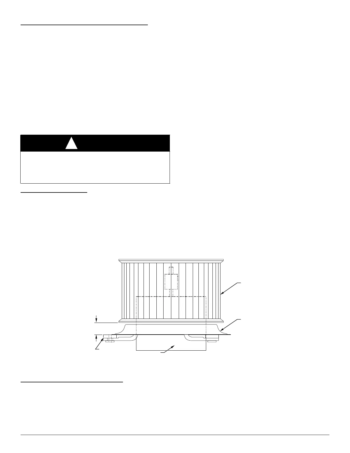
NOTE: If previous shaft was not marked or if replacing previous motor,
set blower wheel position by sliding blower wheel along motor shaft to
1-1/8-in. above rubber grommets (Fig. 25).
4. Hold blower wheel in place and carefully tighten setscrew.
5. Position motor and blower wheel assembly to blower housing as
originally oriented.
6. Secure motor mount to blower housing using bolts previously
removed.
7. Attach green wire to blower housing with screw.
8. Connect electrical and capacitor leads to original terminals.
9. Replace blower access door and tighten all four screws.
10. Reinsert disconnect pullout only after blower access door is
secured. Test blower for proper operation.
A86006
Fig. 25 – Motor, Inlet Ring, and Blower Wheel Assembly
Refrigerant Flow-Control Devices
Thermostatic Expansion Valves (TXV)
NOTE: 2023 models (FE4B, FE5B, FJ4, FJ5, F54, FT4, FT5, PF5) and
beyond (R-454B models) use a mechanical TXV. Refer to the TXV
Installation Instructions. Torque the equalizer fitting to 10–20ft-lb; do
not exceed 20 ft-lb.
All Fan Coils with a TXV are factory equipped with a hard shutoff
(HSO) TXV. The hard shutoff TXV has no bleed port and allows no
bleed-through after system is shutdown.
The TXV is a bi-flow metering device that is used in condensing and
heat pump systems to adjust to changing load conditions by maintaining
a preset superheat temperature at the outlet of the evaporator coil. The
volume of refrigerant metered through the valve seat is dependent upon
the following:
1. Superheat temperature is sensed by a sensing bulb on the suction
tube at the outlet of the evaporator coil. As long as this bulb
contains some liquid refrigerant, this temperature is converted into
pressure pushing downward on the diaphragm, which opens the
valve via push rods.
CAUTION
!
UNIT DAMAGE HAZARD
Failure to follow this caution may result in equipment damage.
Do not use caustic household drain cleaners in the condensate pan or
near the coil. Drain cleaners can quickly destroy a coil.
GROMMET
BLOWER
WHEEL
INLET
RING
MOTOR
1
1
⁄8≤